Screen for hydraulic fluid

a hydraulic fluid and screening element technology, applied in the direction of filtration separation, separation processes, mechanical apparatuses, etc., to achieve the effect of reducing strength, easy pressing, and increasing the strength of the hydraulic fluid screening elemen

Active Publication Date: 2019-03-07
DANFOSS POWER SOLUTIONS GMBH & CO
View PDF5 Cites 3 Cited by
  • Summary
  • Abstract
  • Description
  • Claims
  • Application Information

AI Technical Summary

Benefits of technology

[0019]When carrying out the invention it is further preferred if the apertures are joined onto the screening region axially, radially and / or in the circumferential direction by way of rounded portions. This increases the strength of the hydraulic fluid screening element, since stress peaks and crack-forming tendencies, for example due to the notch effect, are reduced. The regions of the material remaining around the passages can be optimized with regard to the dimensional stability and robustness of the screening element. They may for example be configured as webs of different wall thicknesses or an arcuate form. It is possible to provide radii where notch effects could otherwise reduce the strength. These radii may moreover be variably configured.
[0020]The outer circumferential surface of the screening element preferably forms a conical surface, which has its smallest diameter at the end region of the main body on the outflow side, facing away from the screening region. With a precisely configured, not re-worked conical outside diameter, the screening element can be easily pressed in, for example in a conical installation bore of average variance, without its position in the depth of the bore being subject to any appreciable tolerance. The installation of the screening element is consequently easy and inexpensive. In most applications, no additional measures are required for fixing the screening element. It is self-evident that the concept of the invention also includes a double-sided cone on the outer surface of the main body, in the manner of a double frustum of a cone, with a common greatest diameter at which the frustums are in contact. In this exemplary embodiment it is preferred for technical production-related reasons that the screening region is at the greatest diameter of the double frustum, which may for example be at the center of the screening element, but not necessarily.
[0021]It is favorable for the load-bearing capacity of the hydraulic fluid screening element by high hydraulic pressure or by pressure surges if the screening region has, seen in the direction of throughflow, a convex dome shape, which resists the flow and the pressure of the hydraulic fluid. At least one side of the dome may be formed here in a stepped manner. The stepped formation can achieve the effect that larger dirt particles do not completely clog the apertures, so that a throughflow is still possible around them.
[0022]Suitable for the powder injection-molding process for producing hydraulic fluid screening elements according to the invention are any desired metals that are sinterable. In this specific case, reference is also made to the MIM process (Metal-Injection-Molding). Accordingly, the hydraulic fluid screening element according to the invention may be produced from a metal or metal alloy that is preferably stainless. The chosen material ensures high chemical resistance and prevents corrosion being caused by the hydraulic fluid or constituents admixed in it, such as for example additives.
[0023]The novel screen design according to the invention makes it possible to construct screens for very high pressure loads, even though the load-bearing material has only small wall thicknesses around the passages. There is no need to fear that individual particles may break out, which would lead to contamination, on account of the powder injection-molding process. Because of its robustness, the screen may also be installed in the inflow of valves, in particular control valves and safety valves, that are subjected to the loading of a surge-like, high pulsating volumetric flow.

Problems solved by technology

For removing the untreated parts from the injection mold, demolding angles are required on the component, which is disadvantageous for some other component structures.

Method used


Image

  • Screen for hydraulic fluid
  • Screen for hydraulic fluid

Examples


Embodiment Construction

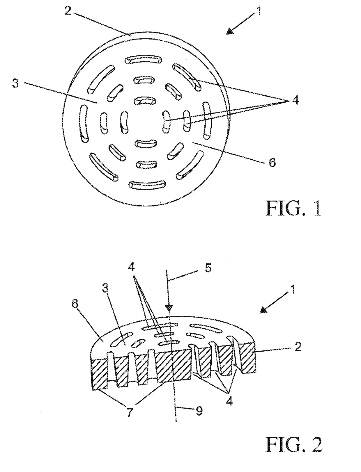
[0029]In FIGS. 1 and 2, an embodiment of the hydraulic fluid screening element 1 according to the invention, which has a generally disc-shaped design, is represented in a perspective view. For example, it has a conical, annularly formed main body 2 in the form of the frustum of a cone, which is covered over its inner cross section by a screening region 3. The screening region 3 is provided with a multiplicity of apertures 4, which by way of example have the form of a kidney or the form of a curved oval and are arranged in multiple concentric circles. In this case, the apertures 4 are conically formed, the screening element 1 preferably being inserted into a hydraulic line in such a way that the side with the smaller passage cross sections forms the inlet side or inflow side 6 of the screening element 1, and accordingly the opposite side with the greater passage cross sections forms the outlet side or the outflow side 7 of the screening element. The preferably conical apertures 4 the...


PUM

PropertyMeasurementUnit
heightaaaaaaaaaa
heightaaaaaaaaaa
heightaaaaaaaaaa

Abstract

The invention relates to a high-pressure hydraulic fluid screening element (1) for inserting into a hydraulic line or into a hydraulic connection of a hydraulic device, having an annular main body (2), which is aligned with respect to its axis of rotation (9) in a longitudinal direction (5). The outside diameter of the main body (2) is greater than its axial length. The inner cross section of the main body (2) is covered over by a screening region (3), which is provided with a multiplicity of apertures (4). In this case, the main body (2) and the screening region (3) are produced integrally by the powder injection-molding process.

Description

CROSS REFERENCE TO RELATED APPLICATION[0001]This application is a continuation-in-part of U.S. Ser. No. 14 / 732,027 filed Jun. 5, 2015 which claims the benefit of German Patent Application No. DE 10 2014 211 395.4 filed Jun. 13, 2014, the contents of these applications are hereby incorporated by reference in their entirety.BACKGROUND OF THE INVENTION[0002]The invention relates to a hydraulic fluid screening element for inserting into a hydraulic line or into a hydraulic connection of a hydraulic device, in particular for inserting into hydraulic connections of hydraulic valves.[0003]Because of their power density and their efficiencies, hydraulic systems or drives are today used in a wide variety of applications. In hydraulic systems, the delivery medium serves not only for power transmission, it also serves for generating and transmitting control signals. Used for this in particular are valves of many different types. It is necessary here to protect both the power-transmitting hydra...

Claims


Application Information

Patent Timeline
Patent Type & Authority Applications(United States)
IPC IPC(8): B01D29/31B01D39/10F15B21/04
CPCB01D29/31B01D39/10F15B21/041B01D2201/184B01D35/02B01D29/03
Inventor THOMS, REINHARDT
Owner DANFOSS POWER SOLUTIONS GMBH & CO
Why Eureka
Try Eureka