
Air-conditioning device

a technology of air-conditioning device and cooling medium, which is applied in the direction of vehicle heating/cooling device, vehicle components, transportation and packaging, etc., can solve the problems of inability to perform cabin-cooling operation with high efficiency, the amount of cooling medium flowing therethrough is greater than the required amount, etc., to increase the pressure of gaseous cooling medium, promote pressure equalization, and reduce the pressure of liquid cooling medium

Inactive Publication Date: 2019-03-07
CALSONIC KANSEI CORP
View PDF6 Cites 6 Cited by
  • Summary
  • Abstract
  • Description
  • Claims
  • Application Information

AI Technical Summary

Benefits of technology

The present invention provides an air-conditioning device that can quickly switch between cooling and heating modes and efficiently cool the cabin. This is achieved by using a special valve that promotes pressure equalization between two cooling agents, even at extreme temperatures. This reduces the switching time and allows for high-efficiency cooling.

Problems solved by technology

However, in the vehicle air-conditioning device disclosed in JP2012-176658A, it is conceivable that the fixed restrictor the opening degree of which is always constant is used as the expansion valve, and because the amount of restriction of the expansion valve is set small so as not to cause the choked flow when the load of the compressor is increased, the amount of the cooling medium flowing therethrough is greater than that is required, and so, it is not possible to perform cabin-cooling operation with high efficiency.

Method used


Image

  • Air-conditioning device
  • Air-conditioning device
  • Air-conditioning device

Examples


Embodiment Construction

[0015]An embodiment of the present invention will be described below with reference to the drawings.

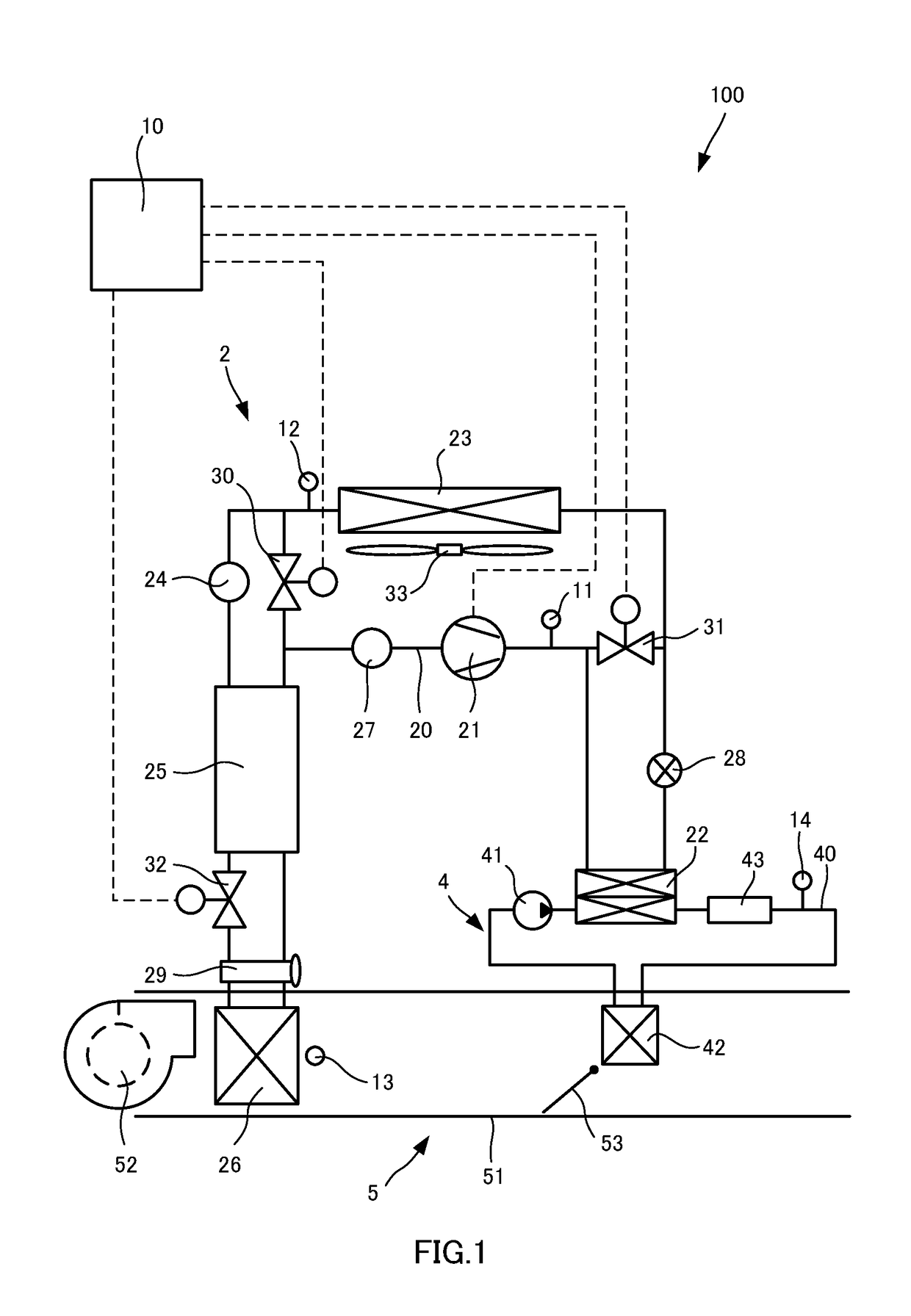
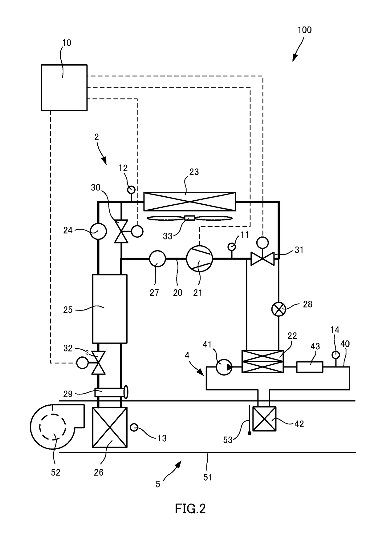
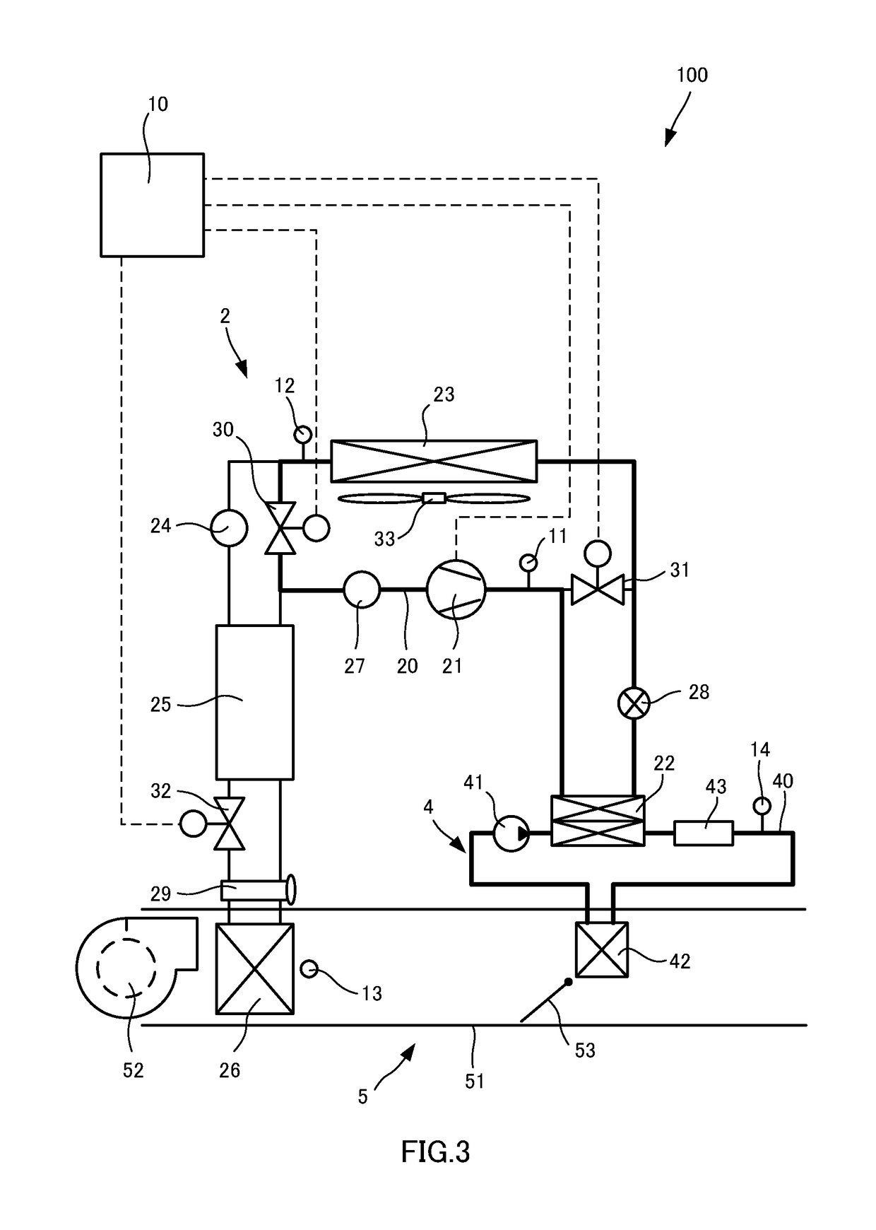
[0016]FIG. 1 is a configuration diagram showing an air-conditioning device 100 according to an embodiment of the present invention.

[0017]The air-conditioning device 100 is a heat pump system capable of performing cabin cooling and cabin heating and includes a refrigeration cycle 2 through which cooling medium circulates, a high-water temperature cycle 4 through which hot water circulates, an HVAC (Heating Ventilation and Air Conditioning) unit 5 through which air used for air-conditioning passes, and a controller 10 serving as a control unit that controls operation of the air-conditioning device 100. For example, the air-conditioning device 100 is mounted on a vehicle and performs air-conditioning in a vehicle cabin. In addition, HFC-134a is used as the cooling medium, and an antifreeze is used as the hot water.

[0018]The refrigeration cycle 2 includes a compressor 21, a fluid-cooled c...


PUM


Abstract

An air-conditioning device includes: a compressor, an external heat exchanger, an evaporator, a fluid-cooled condenser, a thermostatic expansion valve, an internal heat exchanger, a fixed restrictor, a first flow-path switching valve, and a second flow-path switching valve configured to switch flow path of cooling medium so as to bypass the fluid-cooled condenser and the fixed restrictor at cabin-cooling operation time.

Description

TECHNICAL FIELD[0001]The present invention relates to an air-conditioning device.BACKGROUND ART[0002]JP2012-176658A discloses a vehicle air-conditioning device including an expansion valve that depressurizes cooling medium flowing into an evaporator, and an internal heat exchanger that performs heat exchange between the cooling medium on the upstream side of the expansion valve and the cooling medium on the downstream side of the evaporator. With the vehicle air-conditioning device disclosed in JP2012-176658A, cabin-cooling operation and cabin-heating operation are performed by switching flow of the cooling medium in a heat pump cycle. In the vehicle air-conditioning device disclosed in JP2012-176658A, it is conceivable that a fixed restrictor, such as a common orifice or capillary tube, is used as the expansion valve. In the case in which the fixed restrictor is used as the expansion valve as described above, the amount of restriction is set small in advance so as not to cause a ch...

Claims


Application Information

Patent Timeline
Patent Type & Authority Applications(United States)
IPC IPC(8): B60H1/22B60H1/32
CPCB60H1/22B60H1/32B60H2001/2228B60H2001/2246B60H2001/2268B60H1/00921B60H2001/00928B60H2001/00949
Inventor NAKAMURA, KOJIROMAEDA, TOMOHIRO
Owner CALSONIC KANSEI CORP
Learn More