System and method for 3D holographic display using spatial-division multiplexed diffractive optical elements for viewing zone improvement

Active Publication Date: 2019-03-07
ELECTRONICS & TELECOMM RES INST
View PDF1 Cites 7 Cited by
  • Summary
  • Abstract
  • Description
  • Claims
  • Application Information

AI Technical Summary

Benefits of technology

[0008]Embodiments of the present invention are provided to enhance the performance of a 3

Problems solved by technology

On the other hand, the viewing angle of the holographic display is limited.
There are limitations in improving SLM performance based on existing fla

Method used


Image

  • System and method for 3D holographic display using spatial-division multiplexed diffractive optical elements for viewing zone improvement
  • System and method for 3D holographic display using spatial-division multiplexed diffractive optical elements for viewing zone improvement
  • System and method for 3D holographic display using spatial-division multiplexed diffractive optical elements for viewing zone improvement

Examples


Embodiment Construction

[0035]In the following detailed description, only certain exemplary embodiments of the present invention have been shown and described, simply by way of illustration. As those skilled in the art would realize, the described embodiments may be modified in various different ways, all without departing from the spirit or scope of the present invention. Accordingly, the drawings and description are to be regarded as illustrative in nature and not restrictive. Like reference numerals designate like elements throughout the specification.

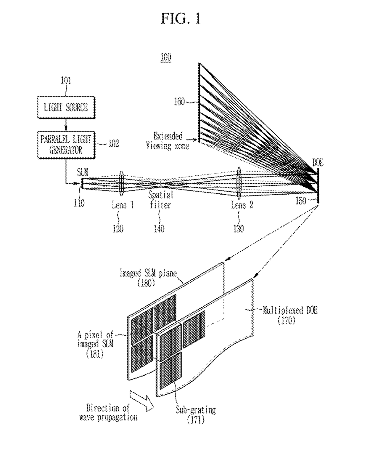
[0036]FIG. 1 shows a 3D holographic display system according to an exemplary embodiment of the present invention.

[0037]A 3D holographic display system 100 according to an exemplary embodiment of the present invention may include a light source 101, a parallel light generator 102, a SLM 110, a relay optical apparatus 120 and 130, a spatial filter 140, and a DOE 150 and 170.

[0038]The light source 101 may emit interference light, and the parallel light genera...


PUM


Abstract

In the present invention, by providing a 3D holographic display system comprising a modulation apparatus configured to modulate light emitted from a light source into a light wave corresponding to a 3D image, an optical apparatus configured to propagate the light wave into the first plane, and a diffraction apparatus configured to multiplex the propagated light wave to extend viewing angle of the 3D holographic display, a limited viewing zone of the holographic display determined by the SLM pixel pitch, may be extended by optical methods, such as using diffractive optical elements (DOE) for spatial-division multiplexing (SDM).

Description

CROSS-REFERENCE TO RELATED APPLICATION[0001]This application claims priority to and the benefit of Korean Patent Application Nos. 10-2017-0112825 and 10-2018-0104668 filed in the Korean Intellectual Property Office on Sep. 4, 2017 and Sep. 3, 2018, respectively, the entire contents of which are incorporated herein by reference.BACKGROUND OF THE INVENTION(a) Field of the Invention[0002]The present invention relates to a 3D holographic display system and method for extending a limited viewing zone of a holographic display through spatial-division multiplexing using a DOE.(b) Description of the Related Art[0003]The holographic display includes at least one SLM (spatial light modulator) that modulates the amplitude or phase of the incident interference light. Depending on the modulation scheme, the SLM may be defined as Electrically Addressed Spatial Light Modulators (EASLMs), Optically Addressed Spatial Light Modulators (OASLMs), Electro-optic SLMs (EOSLMs), Acousto-optic SLMs. EASLM i...

Claims


Application Information

Patent Timeline
IPC IPC(8): G03H1/22G02B27/22
CPCG03H1/2205G03H1/2294G02B27/2214G03H2223/23G03H2001/2207G03H2001/2239G03H1/0244G03H1/0248G03H1/30G02B5/188
Inventor KIM, HYUN EUI
Owner ELECTRONICS & TELECOMM RES INST
Why Eureka
Try Eureka