Process for manufacturing an implant for focal electrical stimulation of a nervous structure

a technology of electrical stimulation and manufacturing technology, applied in the direction of insulating support, conductive layer on the insulating support, therapy, etc., can solve the problems of limiting the focusing of stimulation signals, unable to stimulate the same neurons without any benefit for the patient, and the fabrication technology has a certain number of limitations, so as to reduce the amount of metal used.

Active Publication Date: 2019-03-21
CHAMBRE DE COMMERCE & DIND DE REGION PARIS ILE DE FRANCE +3
View PDF1 Cites 5 Cited by
  • Summary
  • Abstract
  • Description
  • Claims
  • Application Information

AI Technical Summary

Benefits of technology

[0041]The use of said resin mould has numerous advantages.
[0042]It allows a reduction in the amount of metal used.
[0043]It also allows controlled geometric shapes to be obtained, and in particular to obtain submicron resolution.

Problems solved by technology

One of the current limitations for stimulation implants is control over the focusing of stimulation signals.
However, if focusing of stimulation currents is not properly obtained, contiguous electrodes will stimulate the same neurons without any benefit for the patient.
This fabrication technology has a certain number of limitations however.
In particular, it requires destruction of the moulds which cannot be reused and are destroyed at the end of the process to release the implants.
In addition, whilst this technology is adapted for cases having a low number of electrodes (a few tens) it proves scarcely compatible with a higher number of electrodes.
Also, it only allows flexible polymer-based implants to be produced and does not allow the fabrication of implants having rigid substrates that are thinned at the end of the process to become flexible.
Also, this manufacturing technology strongly limits the shapes that can be imparted to the cavities of the implant (these shapes being either square or round).

Method used


Image

  • Process for manufacturing an implant for focal electrical stimulation of a nervous structure
  • Process for manufacturing an implant for focal electrical stimulation of a nervous structure
  • Process for manufacturing an implant for focal electrical stimulation of a nervous structure

Examples


implementation and embodiment

OF IMPLEMENTATION AND EMBODIMENT

General Structure of an Implant

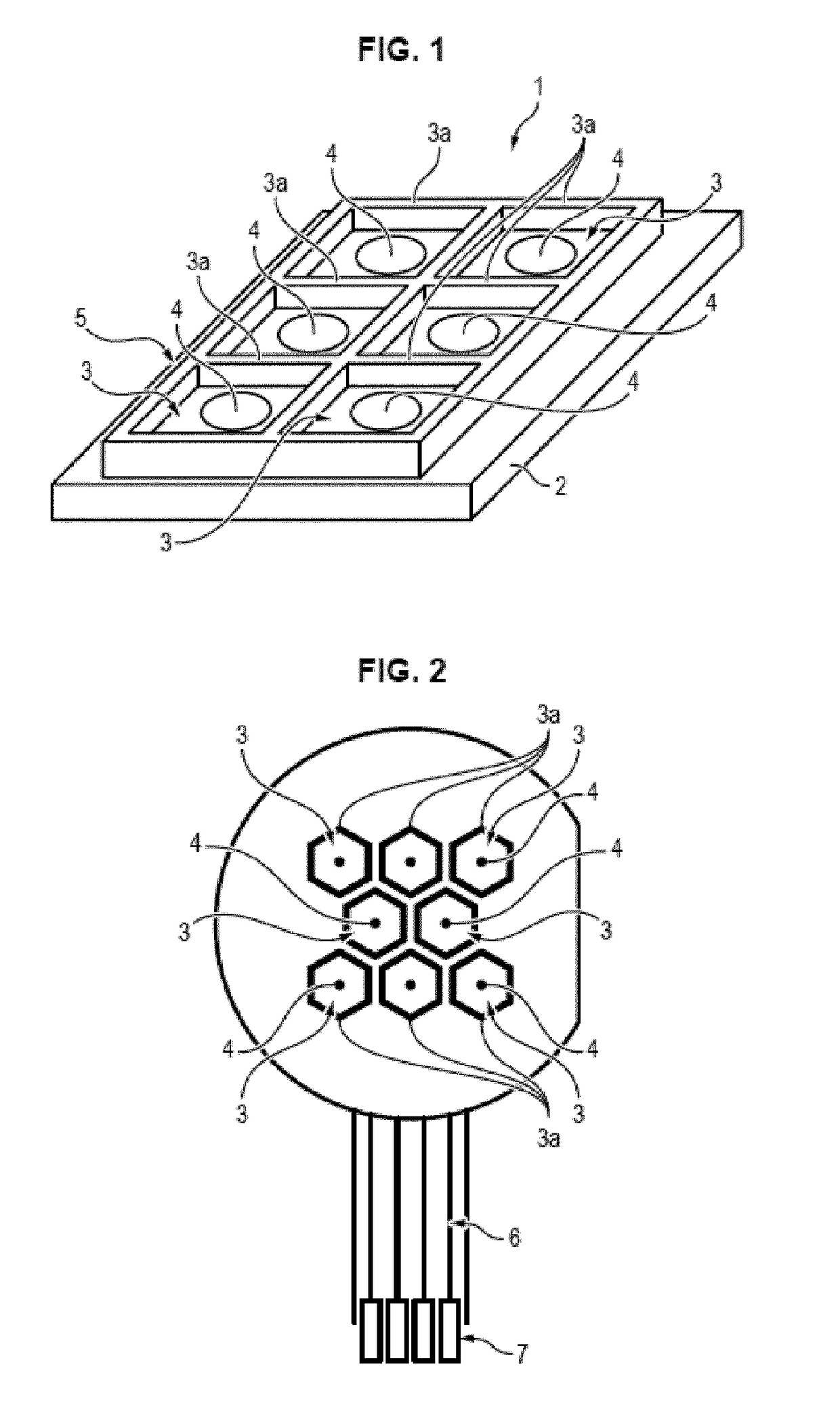
[0077]The implant 1 illustrated in FIGS. 1 and 2 comprises an electrically insulating substrate 2 on which a network 5 of cavities 3 is formed. Stimulation electrodes 4 are arranged at the bottom of these cavities 3.

[0078]The walls3a defining the network 5 and cavities 3 are in metal and / or a polymer material. They extend by projecting from the plane of the electrodes 4, optionally being at least partly above the latter.

[0079]The term “network” used in the entire description means a set of interweaved walls.

[0080]The network in some embodiments may be compared to a grid of polymer walls or a rigid grid with metal walls. In other words, the walls have a certain thickness and here they are thin. The walls are of narrower thickness than the width of the cavities (or the diameter of the cavities if the cavities are round).

[0081]This network may or may not be a ground grid (i.e. a network connected to a ground).

[0082]The term...


PUM

PropertyMeasurementUnit
anglesaaaaaaaaaa
anglesaaaaaaaaaa
heightsaaaaaaaaaa

Abstract

The invention relates to a process for manufacturing at least one implant for focal electrical stimulation of a nervous structure, said implant being of the type including in a supporting structure a network of cavities at the bottom of which are placed microelectrodes, the cavities being bounded by walls erected and located around the microelectrodes, the supporting structure being produced beforehand by implementing the following steps: deposition and etching, in a planar manner, on an insulating substrate, of electrical contacts, of electrical tracks and of microelectrodes, first tracks electrically connecting the microelectrodes and the electrical contacts, second electrical tracks being electrically connected to a ground.

Description

[0001]The present invention relates to implants for focal electrical stimulation of a nervous structure.[0002]In particular, there is proposed a process for manufacturing an implant of this type, and a novel implant structure.GENERAL TECHNICAL FIELD AND PRIOR ART[0003]Implants allowing the electrical stimulation of nervous structures by means of networks of macro- or microelectrodes are currently undergoing strong development.[0004]For example, cochlear implants are now frequently fitted to patients suffering from hearing loss further to deterioration of the hammer and anvil system; in addition, the first retinal implants are currently being tested in man for persons who have lost their sight subsequent to neurodegenerative diseases such as AMD or pigmentary retinopathy. Cortical implants have also been proposed. The progress achieved in recent years with implants for electrical stimulation of nervous structures allows the envisaging of treatment for an increasing number of motor or...

Claims


Application Information

Patent Timeline
Patent Type & Authority Applications(United States)
IPC IPC(8): A61N1/05A61N1/36H01B5/14H01B13/00
CPCA61N1/0543A61N1/36046H01B5/14H01B13/0036A61N1/025A61N1/05H05K3/06H05K3/4682H05K2201/0154
Inventor ROUSSEAU, LIONELLISSORGUES, GAELLECOTTANCE, MYLINEPICAUD, SERGEDEGARDIN, JULIE
Owner CHAMBRE DE COMMERCE & DIND DE REGION PARIS ILE DE FRANCE
Why Eureka
Try Eureka