Method and system for coolant flow control for a prime mover in a vehicle propulsion system

a prime mover and vehicle propulsion technology, applied in the direction of engines, mechanical apparatus, machines/engines, etc., can solve the problems of slow response general instability of coolant flow temperature, etc., to reduce actuator oscillation and temperature fluctuations, improve fuel economy, efficiency, reliability and durability, and greatly improve control over the temperature of a prime mover in a vehicle propulsion system

Inactive Publication Date: 2019-03-21
GM GLOBAL TECH OPERATIONS LLC
View PDF2 Cites 4 Cited by
  • Summary
  • Abstract
  • Description
  • Claims
  • Application Information

AI Technical Summary

Benefits of technology

[0014]In this manner, by selecting control system coefficients based upon a power of the prime mover, control over the temperature of a prime mover in a vehicle propulsion system is greatly improved, which, in turn, improves fuel economy, efficiency, performance, reliability, and durability, reducing actuator oscillations and temperature fluctuations, improving responsiveness, reducing thermal strain, while simultaneously significantly reducing the workload associated with a calibration process that determines the coefficients corresponding to the power of the prime mover.

Problems solved by technology

An overdamped system may result in a coolant flow temperature which is very slow to respond.
An underdamped system may result in a coolant flow temperature which repeatedly overshoots and undershoots the target temperature and may generally be unstable.
An underdamped system will tend to overwork the components in the coolant flow control system which may lead to excessive wear and reduced durability.
Further, an underdamped coolant temperature control may lead to excessive thermal cycling which may have an adverse effect on the components of the coolant system.
However, the calibration workload that is required also necessarily increases with the number of operating conditions for which optimum gain coefficients are determined in this manner.

Method used


Image

  • Method and system for coolant flow control for a prime mover in a vehicle propulsion system
  • Method and system for coolant flow control for a prime mover in a vehicle propulsion system
  • Method and system for coolant flow control for a prime mover in a vehicle propulsion system

Examples


Embodiment Construction

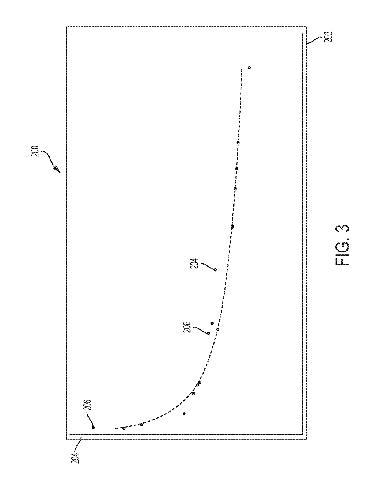
[0024]The inventors discovered that the thermal dynamics of a thermal management system for an internal combustion engine vary according to operating conditions. The gain coefficients which may be optimum for a specific operating condition may result in either over-gained (oscillatory) or under-gained (slow) response at other operating conditions. Therefore, in order to optimally control the temperature of that engine, the gain coefficients which are used should also change in accordance with the change in operating conditions. As a result of this, monitoring and adapting based upon temperatures alone has not proven reliable for changing operating conditions. The challenge, however, was in determining which of the measurable operating conditions most closely correlate to the optimum gain coefficients. The inventors discovered that there is a strong correlation between the power that is produced by a prime mover, such as an internal combustion engine, and the gain of coefficients of ...


PUM


Abstract

A vehicle propulsion system includes a prime mover having a coolant inlet and coolant outlet, a coolant flow controller having a flow control inlet in communication with the prime mover coolant outlet, and a flow control outlet in communication with the prime mover coolant inlet, and a controller that determines a coefficient based upon a power of the prime mover, and that provides a coolant flow command signal to the coolant flow controller based upon the power of the prime mover.

Description

FIELD[0001]The present disclosure relates to a method and system for coolant flow control for a prime mover in a vehicle propulsion system.INTRODUCTION[0002]This introduction generally presents the context of the disclosure. Work of the presently named inventors, to the extent it is described in this introduction, as well as aspects of the description that may not otherwise qualify as prior art at the time of filing, are neither expressly nor impliedly admitted as prior art against this disclosure.[0003]Vehicle propulsion systems may control coolant flow for a prime mover based on a predetermined set of gain coefficients that are determined by operating the prime mover at steady state in a number of operating conditions and determining the optimum set of gain coefficients for each operating condition. For example, in an internal combustion engine having a flow of coolant controlled by a valve, the engine may be operated at a selected speed and load and the proportional and integral ...

Claims


Application Information

Patent Timeline
Patent Type & Authority Applications(United States)
IPC IPC(8): F01P7/16F01P3/20F01P5/10
CPCF01P7/16F01P3/20F01P5/10F01P2007/146F01P2025/08F01P3/02F01P2003/024F01P2003/021F01N13/105F01N3/04F01P5/02F01N3/046F01P7/167F01P2003/027F01P2023/08F01P2025/31F01P2025/33F01P2025/44F01P2025/62F01P2025/64F01P2060/16Y02T10/12
Inventor CRAFT-OTTERBACHER, KATHERINELUTH, KARI A.HEINZEN, ADAM J.
Owner GM GLOBAL TECH OPERATIONS LLC
Why Eureka
Try Eureka