Multimode optical fiber communication device comprising a component for modal dispersion compensation

a multi-mode optical fiber and compensation technology, applied in the field of optical fiber communication, can solve the problems of modal dispersion, varies in the propagation speed of light, and drawbacks of multi-mode fibers, and achieve the effect of increasing the speed

Active Publication Date: 2019-03-28
CAILABS
View PDF0 Cites 1 Cited by
  • Summary
  • Abstract
  • Description
  • Claims
  • Application Information

AI Technical Summary

Benefits of technology

[0017]at least two mirrors enabling a multiple reflection of the beam between the two mirrors,
[0025]In summary, the disclosure makes it possible to increase the speed limit of a multimode optical fiber in an existing facility, or a facility to be created. With regard to the existing facilities, it is compatible with the existing architecture, since adding the optical component for modifying the spatial profile at an upstream or downstream end of an existing fiber is generally sufficient. Such solution also makes it possible to go on using multimode fibers even in geographically extensive data centers (over one kilometer). It makes it possible to reduce the multimode optical fibers design constraints by avoiding modal dispersion to be the major constraint; for example, other properties of the fiber such as losses in the presence of bends or chromatic dispersion can be optimized, with the optical component being used to compensate the modal dispersion.
[0026]The solution according to the disclosure is highly integrated (a single compensation housing) and is, therefore, advantageous in this regard, as compared with solutions that would require several components and, specifically, solutions that would require adding compensation optical fibers. Finally, it introduces no significant losses (as compared to solutions that would use a too slow or too fast mode elimination filter).

Problems solved by technology

But multimode fibers have a drawback, which is modal dispersion: several modes can simultaneously propagate in the fiber, but the propagation speed of light varies according to the propagation mode.
Decoding the digital information in the receiver may become difficult, if the pulses are transmitted at high speed and / or if the fiber is long.
This results in a bandwidth limited by the modal dispersion; such modal bandwidth limits the maximum data rate that can be reached in the fiber, depending on the length thereof.
The solution consisting in changing the fibers to replace the same with multimode fibers having a higher standard, or even with single-mode fibers, is an expensive solution, both with regard to hardware (higher standard fibers are more expensive) and set-up time, in existing networks.
The main drawback is the cost of such filters and, more specifically, the resulting energy loss, since the eliminated modes are, by nature, modes that otherwise transport a part of the radiation energy.
Such energy loss, which is added to natural losses in the long fibers, makes the detection of information in the receiver, at the end of the fiber, more difficult.

Method used


Image

  • Multimode optical fiber communication device comprising a component for modal dispersion compensation
  • Multimode optical fiber communication device comprising a component for modal dispersion compensation
  • Multimode optical fiber communication device comprising a component for modal dispersion compensation

Examples


Embodiment Construction

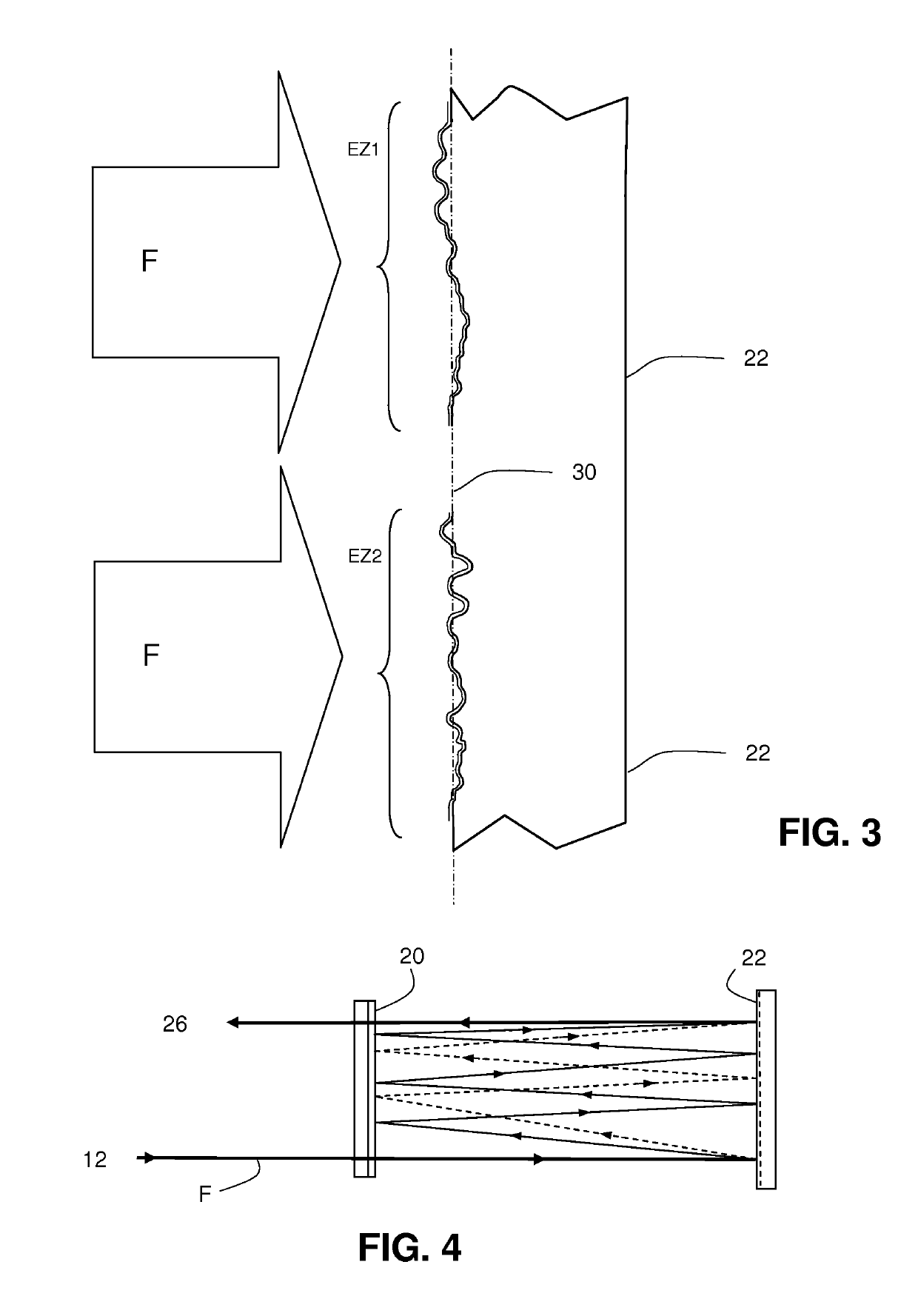
[0036]The spatial profile modification optical component that will be used is based upon components used in the prior art to modify the spatial profile of a coherent light beam.

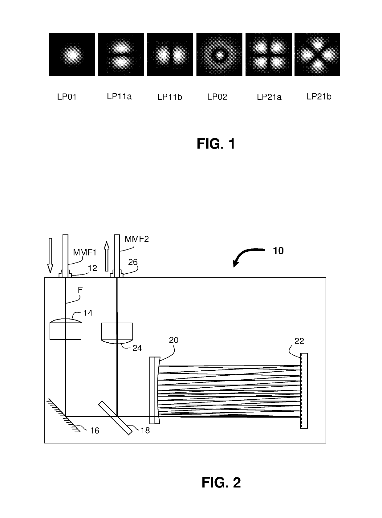
[0037]For the record, the spatial profile of a light beam is an electric field distribution profile in a beam section transverse to the axis of propagation. This is a profile of complex amplitudes of an electric field that can be represented at any point of the section by one intensity and one phase. For example, the intensity profile would be Gaussian in the case of a beam transmitted by a single-mode fiber energized according to the fundamental mode. The profile is, of course, more complex in the case of a multimode beam and it can be broken down into specific profiles corresponding to each mode.

[0038]The modes of propagation in a multimode fiber are commonly reported in the literature and often designated by letters and numbers that indicate the nature of the mode and the order thereof in two dimensions. T...


PUM


Abstract

An optical phase-shifting component is used for shifting the phase and modifying the intensity of the light beam injected into the fiber (MMF2). The component is inserted upstream or downstream of, or at an intermediate position in, the fiber. The component uses two mirrors and multiple beam paths between the mirrors. An optical phase-shifting structure (e.g., a reflective phase mask with a structured surface, which can be a mirror is effective at each reflection of the beam and gradually splits the beam into faster and slower propagation modes. The faster modes are subjected to one or more reflections more than the slower modes and are thereby decelerated. The fast and slow modes are combined again and are then transmitted in a multimode fiber in which the modes have different propagation speeds. The difference in the propagation speeds is thus at least partly compensated.

Description

CROSS-REFERENCE TO RELATED APPLICATIONS[0001]This application is a national phase entry under 35 U.S.C. § 371 of International Patent Application PCT / FR2017 / 050530, filed Mar. 9, 2017, designating the United States of America and published as International Patent Publication WO 2017 / 158261 A1 on Sep. 21, 2017, which claims the benefit under Article 8 of the Patent Cooperation Treaty to French Patent Application Serial No. 1652142, filed Mar. 15, 2016.TECHNICAL FIELD[0002]The application relates to optical fiber communications.BACKGROUND[0003]In many communication networks using optical fibers that transmit digital information by amplitude modulation of a usually infrared light beam, so-called multimode optical fibers are used. Unlike single-mode fibers that have a core with a very small diameter and that spread light in a single mode, which is the fundamental mode, multimode fibers have a core with a larger diameter and can propagate light simultaneously in several propagation modes...

Claims


Application Information

Patent Timeline
Patent Type & Authority Applications(United States)
IPC IPC(8): H04B10/2581H04B10/2543H04B10/2525H04B10/548
CPCH04B10/2581H04B10/2543H04B10/2525H04B10/548G02B26/06H04B10/2507G02B6/14H01S3/13H04B10/25
Inventor MORIZUR, JEAN-FRANCOISBARRE, NICOLAS
Owner CAILABS
Why Eureka
Try Eureka