Rotor segment of an electric machine

a technology of electric machines and rotors, which is applied in the direction of dynamo-electric machines, magnetic circuit rotating parts, and shape/form/construction of magnetic circuits, etc., can solve the problems of increased machining costs of laminated cores, costly manufacturing and assembly processes, and heat removal. , the effect of simple and cost-effective manner

Active Publication Date: 2019-04-04
THYSSENKRUPP PRESTA TECCENTER AG +1
View PDF7 Cites 6 Cited by
  • Summary
  • Abstract
  • Description
  • Claims
  • Application Information

AI Technical Summary

Benefits of technology

[0005]Therefore the problem which the present invention proposes to solve is to eliminate at least some of the above described drawbacks in a rotor segment of an electric machine, especially an electric machine. In particular, the problem which the present invention proposes to solve is to provide a rotor segment of an electric machine, as well as an electric machine, which enables an optimal removal of heat, especially a cooling of the laminated core, in a simple and cost-effective manner, while avoiding a costly machining of the laminated core, especially the creating of any additional cooling ducts inside the laminated core.
[0011]Advantageously, in this case the height extending in the radial direction is dimensioned such that an effective convective cooling is realized. This means that the heat generated by the laminated core is taken up by means of a cooling medium flowing through the gap and transported away from the laminated cores. The cooling medium is advantageously a liquid or gaseous medium. Advantageously, the large-dimensioned gap height, far greater than a clearance fit, serves for an actual freedom from contact between the laminated core and the rotor shaft and therefore provides an electric insulation. Another benefit of this configuration is that neither the outer diameter of the rotor shaft or especially the outer diameter of the hollow cylinder shell nor the inner diameter of the laminated core needs to be fabricated with tight tolerances. Consequently, it is advantageously possible to simplify or avoid costly grinding processes on the rotor shaft, especially the hollow cylinder shell of the rotor shaft. Likewise, the internal geometry of the punched metal sheets of the laminated core can advantageously be produced more economically on account of a more free geometry.
[0012]In order to make possible an optimally effective convection in the produced gap, a sufficiently designed flow cross section must be provided. Taking into account wall friction resistances of the flow of cooling medium in this gap, which can also be called an annular gap, and owing to other design fundamentals for a convective flow of cooling medium, a flow area of around 400-1000 mm2 advantageously results. Advantageously, it is conceivable to relate the gap height being dimensioned for a sufficiently large flow cross section to the outer diameter of the rotor shaft. In this way, it is possible to take into account any possible shapes and dimensions of electric machines and thus rotor shaft geometries, which may be highly diversified. Furthermore, it is possible for the gap height to be at least 1.5-3 mm. A gap height of around 2.5 mm should be seen as being advantageous for a reference diameter of the gap of around 80 mm, consequently resulting in a flow cross section of around 600 mm2. With increasing rotor shaft diameter, one must also generally expect an increasing need for heat removal, so that a ratio of around 1:8 of rotor shaft diameter to flow cross section may serve advantageously as a first design principle for a gap height of 2.5 mm.
[0018]Advantageously, the intermediate element comprises a non-ferromagnetic material. Especially advantageously, the permeability coefficient of the intermediate element is below 5, so that magnetic leakages which would reduce the efficiency of the electric machine are avoided. Consequently, the intermediate element advantageously serves for the electromagnetic shielding of parasitic magnetic flux occurring in the axial direction. The width of the intermediate piece in the axial direction, including the protrusions, is advantageously around 2-6 mm, especially advantageously around 4 mm. It is conceivable for the intermediate element to be made from a plastic material or aluminum material—at least in part. Furthermore, it is also possible to realize, regardless of the design of the radial passage openings indicated in the specification, complex passage opening geometries in order to ensure an adequate heat removal. Thanks to the use of an intermediate element, a specific material chosen for the pressure disks in regard to its ferromagnetic properties is hence irrelevant. Consequently, it is also conceivable to use pressure disks made from a steel material.
[0026]Thanks to the configuring of such a cooling duct, a cooling circuit is closed. Furthermore, a convective cooling of the winding heads as well as the removal of heat from the cooling medium via the cooling of the stator shell is also possible. Advantageously, moreover, no opening of the housing is required, so that the electric machine is consequently encapsulated. Thanks to a permanent circulating of air in the interior of the electric machine, it is possible to effectively cool places where much heat is produced, bringing about a temperature equalization inside the electric machine.

Problems solved by technology

However, this freedom from contact also has the drawback that the waste heat arising on account of the electromagnetic function from the laminated cores cannot be distributed by means of corresponding thermal conduction across the rotor shaft and from this shaft across corresponding bearing points to the housing, for example, so that heat might be removed from the laminated core itself.
However, the production and arrangement of such laminated core segments requires a costly manufacturing and assembly process.
This, in turn, requires an increased machining expense for the laminated core, especially the individual plates of the laminated core, which furthermore need to be arranged relative to each other in the laminated core so that the passage of the cooling medium becomes possible.

Method used


Image

  • Rotor segment of an electric machine
  • Rotor segment of an electric machine
  • Rotor segment of an electric machine

Examples


Embodiment Construction

[0028]A rotor segment according to the invention and an electric machine according to the invention shall now be explained more closely with the aid of drawings. There are shown, schematically:

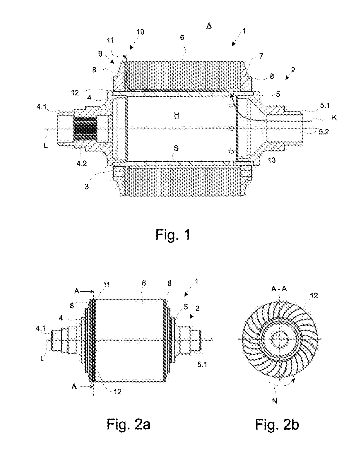
[0029]FIG. 1 in a cross sectional representation, one embodiment of a rotor segment according to the invention,

[0030]FIG. 2a in a top view, the embodiment of a rotor segment according to the invention as shown in FIG. 1,

[0031]FIG. 2b in a top view, the section A to A shown in FIG. 2a

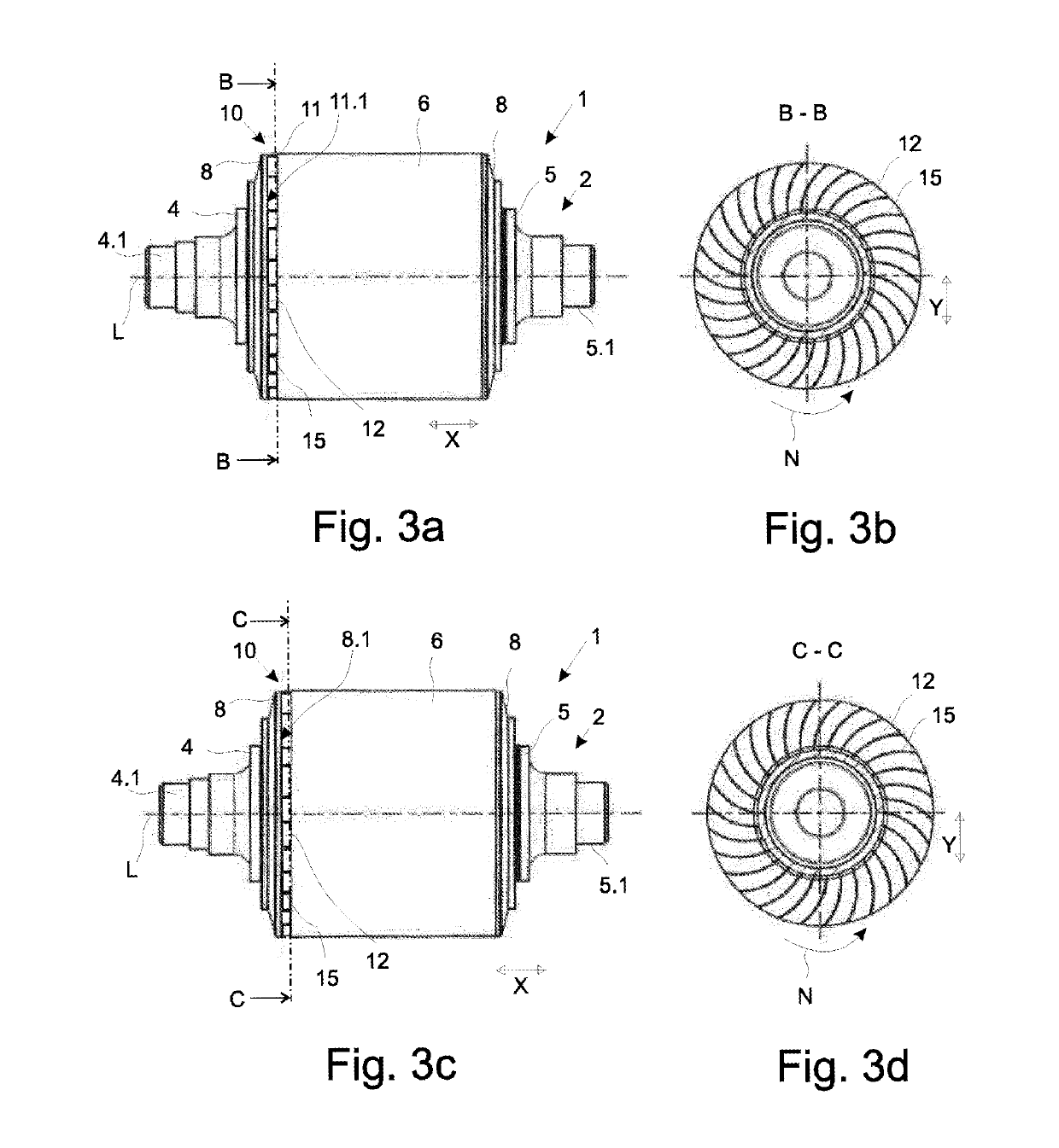
[0032]FIG. 3a in a top view, another embodiment of a rotor segment according to the invention,

[0033]FIG. 3b in a top view, the section B to B shown in FIG. 3a,

[0034]FIG. 3c in a top view, another embodiment of a rotor segment according to the invention,

[0035]FIG. 3d in a top view, the section C to C shown in FIG. 3c,

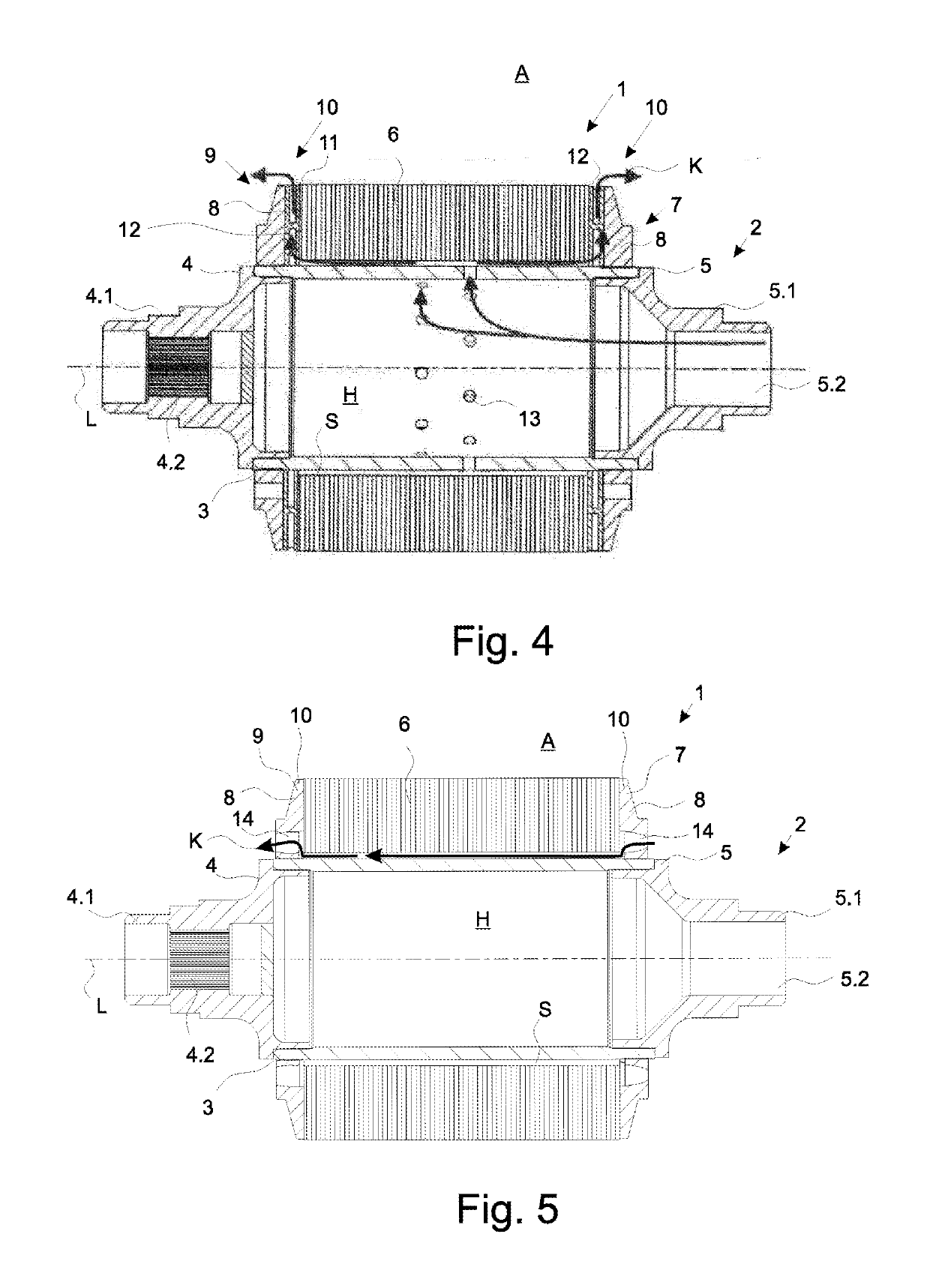
[0036]FIG. 4 in a cross sectional representation, another embodiment of a rotor segment according to the invention,

[0037]FIG. 5 in a cross sectional representation, another embodiment of a rotor segm...


PUM


Abstract

A rotor segment of an electric machine may include a rotor shaft and a laminated core, which is arranged on the rotor shaft in such a way that a gap dimensioned sufficiently large in the radial direction for the passage of a cooling medium is produced between an outer surface of a hollow cylinder shell and an inner surface of the laminated core. The rotor segment may further include two pressure elements that are held on the rotor shaft in a stationary manner such that the pressure elements axially clamp the laminated core. Further, at least one of the pressure elements is designed as a holding segment allowing cooling medium to pass through.

Description

[0001]The present invention relates to a rotor segment of an electric machine, wherein the rotor segment has a constructed rotor shaft. Moreover, the invention relates to an electric machine with a rotor segment with a constructed rotor shaft.PRIOR ART[0002]Basically, the design of hollow cylindrical rotor shafts for the purpose of weight reduction of rotating masses is known. It is further to be assumed as basically known that laminated cores can be fastened on the rotor shaft such that no press fit is needed radially between the shaft outer diameter and the laminated core inner diameter. In this case, the laminated core is axially compressed by means of two pressure disks, wherein friction-locking transmittal of the torque generated in the laminated cores occurs across the pressure disks and the shaft connected rotationally firmly to them to the power takeoff point, which is advantageous for the gear meshing. Thus, for example, a single-segment impeller is represented in WO 2014 / 1...

Claims


Application Information

Patent Timeline
Patent Type & Authority Applications(United States)
IPC IPC(8): H02K1/32H02K9/12
CPCH02K1/32H02K9/12H02K9/19
Inventor PAUL, DANIELMEUSEL, JURGEN
Owner THYSSENKRUPP PRESTA TECCENTER AG
Why Eureka
Try Eureka