Surface treatment process of CMP Polishing pad

Inactive Publication Date: 2019-04-11
CHENGDU TIMES LIVE SCI & TECH
View PDF0 Cites 1 Cited by
  • Summary
  • Abstract
  • Description
  • Claims
  • Application Information

AI Technical Summary

Benefits of technology

The present invention provides a surface treatment process for a CMP polishing pad to improve the stability of the polishing pad in the whole polishing process. By sanding the surface of the substrate with different meshes, the initial surface roughness of the substrate is consistent with the surface roughness of the substrate during use. This solves the problem of unstable initial grinding rate, leading to a significant improvement in the stability of the polishing process of the substrate. The surface treatment process is simple to operate, easy to monitor, and strong in process implementation.

Problems solved by technology

Due to the strict requirements of the thickness of the product after being sliced, the current research on the slicing process mainly focuses on the thickness control, and the surface roughness of the product after being sliced is not monitored and controlled.
Due to different initial surface roughness of the polishing pad, the contact areas of the product to be polished are different, resulting in different initial grinding rates, so that the initial grinding rate of most polishing pads is unstable during use.

Method used


Image

  • Surface treatment process of CMP Polishing pad
  • Surface treatment process of CMP Polishing pad

Examples


first embodiment

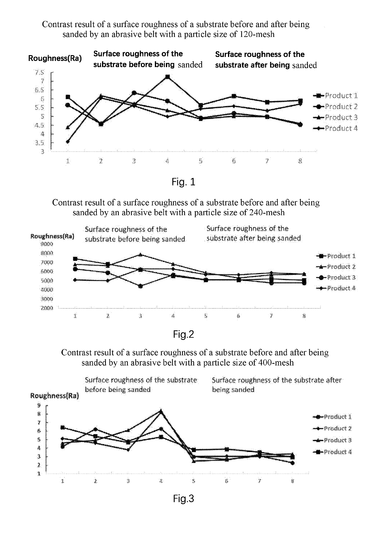
[0025]In the roughing process, a first abrasive belt with a particle size of 120-mesh and a substrate with a thickness of 2.65 mm are used, the substrate is placed in a sanding machine, a height of the first abrasive belt is adjusted to 2.56 mm, a front side of the substrate is sanded for a period of time and then the height of the first abrasive belt is adjusted to 2.47 mm, and then a reverse side of the substrate is sanded, and the thickness of the substrate is 2.47 mm measured by a vernier caliper.

[0026]In the fine process, a second abrasive belt with a particle size of 240-mesh is used, the above substrate is placed in the sanding machine, a height of the second abrasive belt is adjusted to 2.43 mm, the front side of the substrate is sanded for a period of time and then the height of the second abrasive belt is adjusted to 2.39 mm, and then the reverse side of the substrate is sanded, and the thickness of the substrate is 2.39 mm measured by the vernier caliper.

[0027]In the fini...

second embodiment

[0028]In the roughing process, a first abrasive belt with a particle size of 120-mesh and a substrate with a thickness of 2.65 mm are used, the substrate is placed in a sanding machine, a height of the first abrasive belt is adjusted to 2.56 mm, a front side of the substrate is sanded for a period of time and then the height of the first abrasive belt is adjusted to 2.47 mm, and then a reverse side of the substrate is sanded, and then the height of the first abrasive belt is adjusted to 2.39 mm, and then the front side of the substrate is sanded, and the thickness of the substrate is 2.39 mm measured by a vernier caliper.

[0029]In the fine process, a second abrasive belt with a particle size of 240-mesh is used, the above substrate is placed in a sanding machine, a height of the second abrasive belt is adjusted to 2.36 mm, the front side of the substrate is sanded for a period of time and then the height of the second abrasive belt is adjusted to 2.33 mm, and then the reverse side of...


PUM


Abstract

A surface treatment process of a CMP (chemical mechanical polishing) polishing pad includes steps of rough-machining, fine-machining and finish-machining a substrate in sequence with an abrasive belt with a particle size of 120-mesh, an abrasive belt with a particle size of 240-mesh and an abrasive belt with a particle size of 400-mesh, respectively till a target thickness of the substrate is obtained. In each processing stage, the surface of the substrate is sanded through effectively adjusting the height of the corresponding abrasive belt so as to effectively control a surface roughness of the substrate. Moreover, through the surface treatment process provided by the present invention, the initial surface roughness is consistent with the surface roughness in the usage process of the substrate, so as to solve the problem that the initial grinding rate is unstable, thereby significantly improving the stability of the substrate in the CMP process.

Description

CROSS REFERENCE OF RELATED APPLICATION[0001]The present invention claims priority under 35 U.S.C. 119(a-d) to CN 201810971728.7, filed Aug. 24, 2018.BACKGROUND OF THE PRESENT INVENTIONField of Invention[0002]The present invention relates to the processing and manufacturing field of CMP (chemical mechanical polishing) polishing pads, and more particularly to a surface treatment process of a CMP polishing pad.Description of Related Arts[0003]Chemical mechanical polishing (CMP) is a micro-nano processing technology that combines mechanical grinding with chemical oxidation to remove the surface material of machined workpieces. The surface of the machined workpieces is ultra-flat and ultra-smooth through the CMP process, so that the CMP process is mainly used in the field of IC and MEMS manufacturing. The polishing procedure combines chemical corrosion with mechanical friction, the machined workpiece is fixed to a face-down grinding head and fixed to a rotary machine station. The surface...

Claims


Application Information

Patent Timeline
IPC IPC(8): B24B37/04
CPCB24B37/042B24B21/04B24D11/001B24B21/006B24B37/26B24B51/00B24D18/00
Inventor ZHANG, XUEYANZHANG, LIJUAN
Owner CHENGDU TIMES LIVE SCI & TECH
Why Eureka
Try Eureka