Instrumented intra-oral appliance computationally designed for optimized fitting and functionality

an intraoral appliance and computational design technology, applied in the field of custom instrumented intraoral appliances, can solve the problems of reducing wearer compliance, lack of patient compliance, and reducing comfort for wearers, and achieve the effects of enhancing the location of sensors, increasing compliance, and increasing both user comfort and recording accuracy

Active Publication Date: 2019-04-11
BIOMECHANICS CONSULTING & RES LLC
View PDF7 Cites 21 Cited by
  • Summary
  • Abstract
  • Description
  • Claims
  • Application Information

AI Technical Summary

Benefits of technology

[0024]The geometry of each person's mouth is unique. In one embodiment, the invention herein teaches an instrumented intra-oral appliance, which is optimized to increase compliance, meaning wearing the appliance, while also enhancing the location of sensors to record an event (e.g., traumatic head impact), or biological sign (e.g., blood oxygen level), or environmental conditions (e.g., amount of carbon monoxide inhaled). Because the interior of the mouth is sensitive to contact, an intra-oral appliance that accounts for mouth geometry to determine where to place certain sensors is needed. The invention described herein teaches a way to computationally optimize the placement of the sensors so that the appliance does not irritate the user. Moreover, because some areas of the mouth are more advantageous to place certain sensors (e.g., a near infrared sensor to record heart rate is best located near a superficial artery), an appliance is taught with such sensors located where they will best perform their functions as determined based on, for example, an intra-oral scan.
[0025]Past attempts have taken a one-size-fits-all approach and the result is lack of patient compliance—for example a football player will not wear an instrumented mouth guard that is uncomfortable. Other approaches that have endeavored to make a unique appliance based on the user's dental geometry have not accounted for how differences will affect optimal locations for sensors. The present invention teaches a way to make an intra-oral appliance that resolves the shortcomings of the prior art, by creating an intra-oral appliance that is then computationally analyzed to optimize placement of sensors to increase both user comfort and accuracy of recordings by the sensors.

Problems solved by technology

It does not however apply this technique in a unique or individual method that would optimize data integrity for each user and consider comfort.
Adding material to the occlusal surface of the molars could decrease comfort for wearers, and reduce wearer compliance.
Past attempts have taken a one-size-fits-all approach and the result is lack of patient compliance—for example a football player will not wear an instrumented mouth guard that is uncomfortable.
Other approaches that have endeavored to make a unique appliance based on the user's dental geometry have not accounted for how differences will affect optimal locations for sensors.

Method used


Image

  • Instrumented intra-oral appliance computationally designed for optimized fitting and functionality
  • Instrumented intra-oral appliance computationally designed for optimized fitting and functionality
  • Instrumented intra-oral appliance computationally designed for optimized fitting and functionality

Examples


example 1

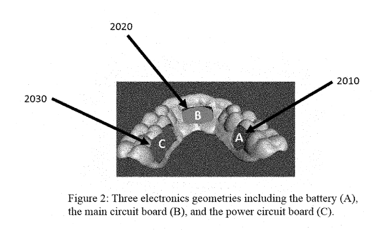
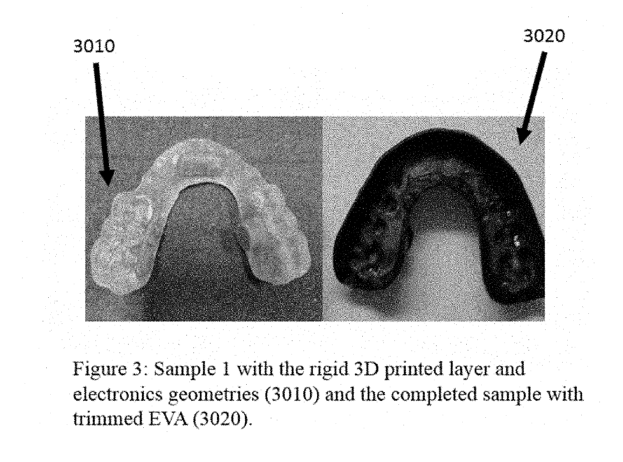
[0059]The first example comprises at least one rigid layer. Such a layer includes recesses that accept the electronics geometries (FIG. 2). In this example, the computational optimization determines, based, for example, on surface geometry of the dentition, that the battery is optimally placed between the 1st and 2nd molar on palatal surface of the left side (2010 in FIG. 2). The main circuit board is optimally placed behind the middle incisors (2020), and the power circuit board is placed on the palatal side of the 1st and 2nd molar on the right side (2030). These locations are defined as optimal by calculating the volume of material required around each component to maintain a smooth palatal surface while maintaining minimum material thickness. The appliances may be 3D printed and then cured, if necessary. Once the appliance is printed, the electronics are attached and the appliance may be custom trimmed (see FIG. 3, 3010). This device is designed such that the rigid layer is in d...

example 2

[0060]In this example (see FIG. 4), the intra-oral scan provided visual evidence of sensitivity on the gingival margin on the palatal surface of the teeth. It is computationally determined that the optimal location for the electronic components are to be bonded to the buccal surface of the rigid layer with a battery on the right side, the main circuit board in front of the middle incisors, and the power circuit board on the left (4010). The 2nd example has a layer of EVA in contact with the teeth and gingiva to mitigate irritation to diseased gingival tissue, then the rigid layer, and finally a layer of EVA is thermoformed over the top and trimmed.

example 3

[0061]In this example (see FIG. 4), it is determined that based on the user's dentition geometry having a small distance across the width of the palate and molars with larger exposed height, that comfort of the user can be optimized by a combination of electronics component selection and placement. With a small palate width, components placed on the palatal surface will interact more with the tongue and negatively influence speech. Therefore, the power circuit board is optimally placed in the same position as in the second example, on the buccal surface. The main circuit board is located on the buccal surface of the right first molar. The battery can be located as in the first and second example but being replaced with a thinner, wider battery geometry, which fits within the palatal surface of the first and second molars without interacting with the tongue due to the reduced height. (4020). Accordingly, different electronic components may be chosen, including by computer model, base...


PUM

PropertyMeasurementUnit
surface areaaaaaaaaaaa
frequencyaaaaaaaaaa
chemicalaaaaaaaaaa

Abstract

An instrumented intra-oral appliance that has been designed computationally to optimize the location and coupling of sensors to optimize data integrity while maximizing comfort for the wearer. The 3D anatomical geometry can be collected directly with an intra-oral scanner or indirectly through an impression and scan of a dental stone model. A generalized design can be created to fit a target audience by obtaining 3D anatomical geometries of the target populations and performing a statistical shape analysis. Once the generalized design of the electronics is created, a unique design can be generated for each individual by locating the electronics such that they collect the best quality data possible. The individual designs can also be generated that maximize comfort for the wearer by minimizing size and volume, avoiding areas that could be painful, and ensuring proper retention of the device. Although not required, the device could be 3D printed to convert the computational design directly to an appliance.

Description

CROSS-REFERENCE TO RELATED APPLICATION[0001]The present application relies on the disclosures of and claims priority to and the benefit of the filing date of U.S. Provisional Application No. 62 / 570,124, filed Oct. 10, 2017. The disclosures of that application are hereby incorporated by reference herein in their entireties.BACKGROUNDField of the Invention[0002]The present invention is directed to a custom instrumented intra-oral appliance that is designed to increase compliance by the wearer. It is also designed such that the sensor locations are optimized to accurately record human performance data or health metrics, including but not limited to, blood oxygen level, heart rate, head kinematics, etc. In one embodiment, sensors are strategically placed in optimal location(s) to record and / or evaluate head kinematics experienced during impact events, with an emphasis on avoiding recording false positives.[0003]In another embodiment, a near infrared sensor is located over or near a supe...

Claims


Application Information

Patent Timeline
Patent Type & Authority Applications(United States)
IPC IPC(8): B29C64/386A61C9/00A61B5/00A63B71/08A61C19/06B33Y10/00B33Y50/00B33Y80/00
CPCB29C64/386A61C9/0053A61B5/682A63B71/085A61C19/066B33Y10/00B33Y50/00B33Y80/00A61B2562/12A61B5/0205A63B2225/50A63B2209/00A63B2220/53A63B2230/202A63B2220/30A63B2220/833A63B2230/207A63B2230/06A63B2230/10A63B2225/20A63B2230/50A63B2220/40A63B2220/80A61C9/004A61C9/0046G06F30/17A61C13/0004G06T7/0012G06T2207/30036
Inventor DAU, NATHANRYDIN, RICHCRANDALL, JEFF
Owner BIOMECHANICS CONSULTING & RES LLC
Why Eureka
Try Eureka