Single facer for producing single face corrugated paperboard, and related method

a corrugated paperboard and single facer technology, applied in the direction of paper/cardboard layered products, layered products, chemistry apparatus and processes, etc., can solve the problems of high thermal loss, particularly complex system, loss of thermal energy, etc., and achieve the effect of reducing energy consumption and smoothing the operation of the single facer

Active Publication Date: 2019-04-11
GUANGDONG FOSBER INTELLIGENT EQUIP CO LTD
View PDF3 Cites 8 Cited by
  • Summary
  • Abstract
  • Description
  • Claims
  • Application Information

AI Technical Summary

Benefits of technology

[0017]The laminar members form a sealing inside the respective annular grooves, which reduces the consumption of air sucked by the suction box, thus reducing the thermal power losses. As the laminar members extend towards the suction box, they minimize the airflow necessary to generate a sufficient suction degree for keeping the corrugated paper sheet adhering to the surface of the second corrugating roller.
[0030]In practical embodiments, each laminar member has a radially outer edge in contact with the sealing member. The radially outer edge can be shaped like an arc. The reciprocal contact between the radially outer edge of the laminar members and the sealing member further reduces the amount of air that shall be sucked to have a sufficient level of vacuum in the annular grooves, thus reducing heat losses. Each laminar member preferably comprises also a continuous or discontinuous radially inner edge adapted to slide on a bottom of the respective groove. The radially inner edge can be used for scraping and cleaning the bottom of the annular groove. A discontinuous radially inner edge reduces the contact and sliding surface between laminar member and annular groove, thus reducing losses due to friction.

Problems solved by technology

This system has many drawbacks, in particular in case of breakage of the paper sheet.
The generated airflow causes drawbacks.
The system is particularly complex and entails high thermal losses due to the need of sucking a great quantity of air in the area surrounding the corrugating roller.
The presence of suction ducts results in a loss of thermal energy from the corrugating rollers and therefore negatively affects the energy consumption of the machine.
In this case again, even if sealing systems are provided, there is a high air consumption with consequent heat removal from the corrugating roller.
Moreover, the detachment of the single face corrugated paperboard from the corrugating roller is particularly difficult and there are frequent breakages of the single face corrugated paperboard, with consequent jam of the single facer.
These also limit the area where the suction is generated through the suction box.
This known system still has drawbacks, in particular due to the air consumption and, thus, to the consequent thermal losses.
Moreover, the conditions under which the corrugated paper sheet and the smooth paper sheet are glued together are not optimal.
Also detaching the single face corrugated paperboard from the corrugating roller downstream of the pressure or gluing nip is difficult.
The detachment of the single face corrugated paperboard is made difficult by the fact that, in the point where the single face corrugated paperboard shall be detached from the corrugating roller, the suction effect is still very strong.

Method used


Image

  • Single facer for producing single face corrugated paperboard, and related method
  • Single facer for producing single face corrugated paperboard, and related method
  • Single facer for producing single face corrugated paperboard, and related method

Examples


Embodiment Construction

[0044]The detailed description below of example embodiments is made with reference to the attached drawing. The same reference numbers in different FIGS. identify equal or similar elements. Moreover, the drawings are not necessarily to scale. The detailed description below does not limit the invention. The protective scope of the present invention is defined by the attached claims.

[0045]In the description, the reference to “an embodiment”, “the embodiment”, or “some embodiments” means that a particular feature, structure or element described with reference to an embodiment is comprised in at least one embodiment of the described subject matter. The sentences “in an embodiment” or “in the embodiment” or “in some embodiments” in the description do not therefore necessarily refer to the same embodiment or embodiments. The particular features, structures or elements can be furthermore combined in any suitable way in one or more embodiments.

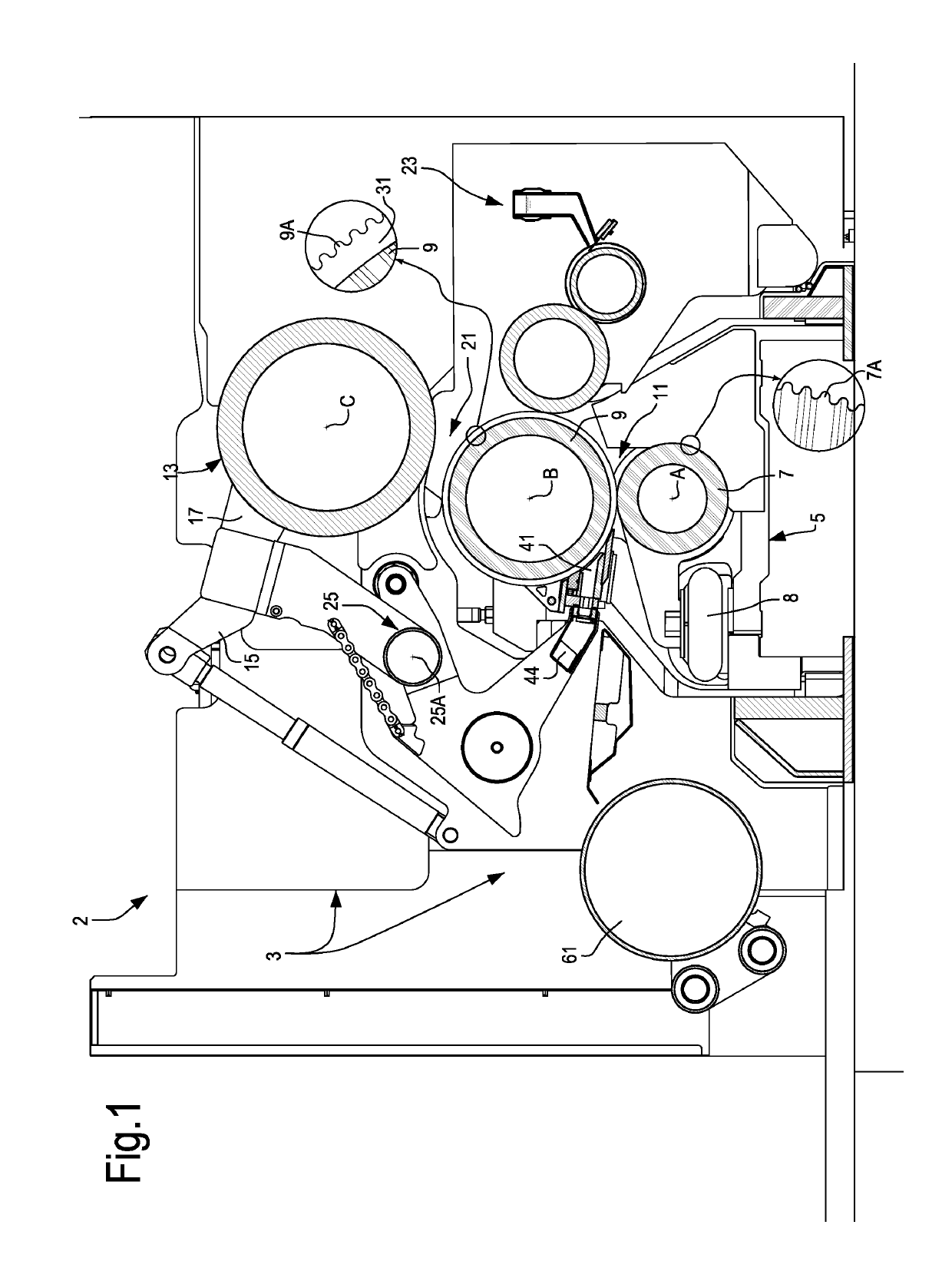
[0046]FIG. 1 shows a schematic side view and pa...


PUM


Abstract

A single facer including a first corrugating roller with a first rotation axis and a second corrugating roller with a second rotation axis. The two corrugating rollers form a corrugating nip, through which a paper sheet passes. The single facer also includes a pressing member, co-acting with the second corrugating roller and forming a pressure nip therewith, as well as a glue applicator co-acting with the second corrugating roller. With the second corrugating roller a suction box is associated, extending approximately parallel to the second rotation axis of the second corrugating roller and defining a suction area around the second corrugating roller. A series of laminar members, each of which is inserted in a respective one of the annular grooves of the second corrugating roller, are arranged between the pressing member and the first corrugating roller and extend in the respective annular grooves towards the suction box.

Description

FIELD OF THE INVENTION[0001]The present invention relates to the field of corrugated paperboard production. In particular, the invention relates to improvements to single facers for producing single face paperboard, and related methods.BACKGROUND TO THE INVENTION[0002]For producing corrugated paperboard, so-called single facers are used that, through an arrangement of corrugating rollers and gluing members, convert two smooth paper sheets into a single face corrugated paperboard, formed by a fluted paper sheet and a smooth paper sheet, also called liner.[0003]For producing a continuous single face corrugated paperboard, two continuous paper sheets are fed to the single facer. The first sheet is fluted by means of a pair of corrugating rollers, each of which is provided with flutes or teeth and meshing with each other at said teeth or flutes in a corrugating nip. The first sheet is corrugated by passing through the corrugating nip. Downstream of the corrugating nip, a glue applicator...

Claims


Application Information

Patent Timeline
Patent Type & Authority Applications(United States)
IPC IPC(8): B31F1/28
CPCB31F1/2854B31F1/2877B31F1/2818B31F1/2863B31F1/2804B32B29/08B32B7/12B31F1/20
Inventor ADAMI, MAURO
Owner GUANGDONG FOSBER INTELLIGENT EQUIP CO LTD
Why Eureka
Try Eureka