Braking force control apparatus for vehicle

a technology of braking force control and control apparatus, which is applied in the direction of brake systems, braking components, tractors, etc., can solve the problems of inability to prevent inability to normalize braking pressure control of relevant wheels, and inability to reduce the possibility of excessive braking slip of each wheel by the control of upstream. , to achieve the effect of reducing a possibility, reducing the braking force of the vehicle, and reducing the braking slip

Inactive Publication Date: 2019-04-11
TOYOTA JIDOSHA KK
View PDF0 Cites 3 Cited by
  • Summary
  • Abstract
  • Description
  • Claims
  • Application Information

AI Technical Summary

Benefits of technology

[0029]According to the above aspect, as compared to where the pressure increasing side mode is selected out of the control modes of the two wheels for at least one of the first and second systems, the braking force of the vehicle can be reduced, so that it is possible to reduce a possibility that a running stability of the vehicle deteriorates due to an excessive braking force.

Problems solved by technology

If an abnormality occurs in a pressure increasing-holding valve or a pressure decreasing valve of any of the wheels, a braking pressure of the relevant wheel cannot be normally controlled.
Therefore, it is impossible to prevent a braking slip of each wheel from becoming excessive in a situation where a braking operation amount of a driver is excessive.
Conventionally, no study has been made to reduce a possibility that a braking slip of a wheel becomes excessive by the control of the upstream pressure when a specific abnormality occurs in the downstream braking actuator.

Method used


Image

  • Braking force control apparatus for vehicle
  • Braking force control apparatus for vehicle
  • Braking force control apparatus for vehicle

Examples


first embodiment

Operation of First Embodiment

[0088]Next, the operation of the braking force control apparatus 10 according to the first embodiment will be described with respect to various cases.

26A and 26B are Normal>

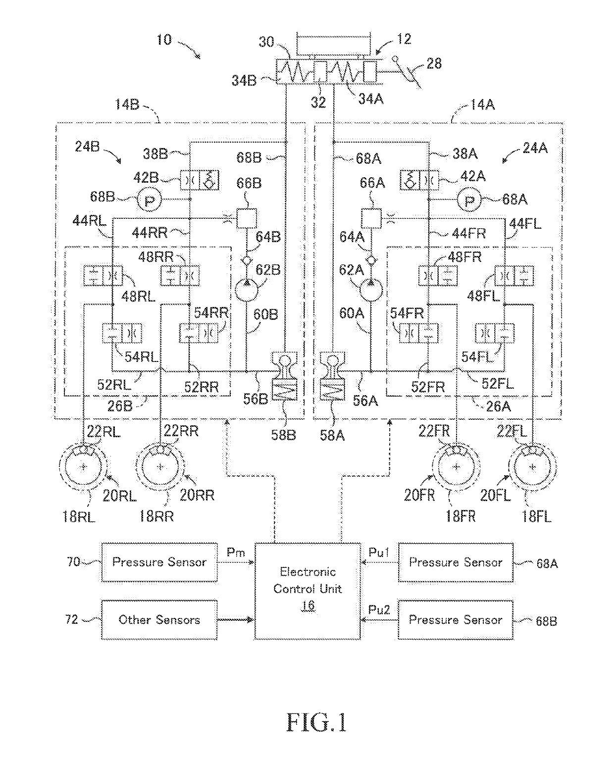
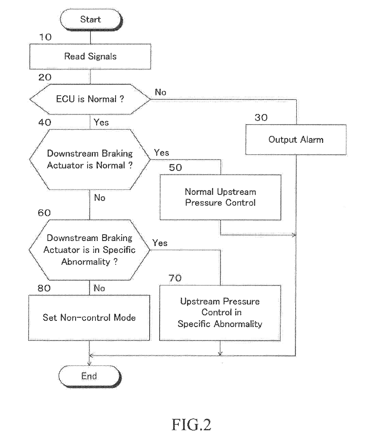
[0089]In step 40, an affirmative determination is made, and in step 50, the communication control valves 42A and 42B are controlled so that the upstream pressures Pu1 and Pu2 become the target upstream pressures Pu1t and Pu2t, respectively.

26A and / or 26B are in a Specific Abnormality>

[0090]In steps 40 and 60, a negative determination and an affirmative determination are made, respectively. In step 70, the prescribed control modes of the upstream braking actuators 24A and 24B are determined according to equations (1) and the first and second upstream pressures Pu1 and Pu2 are controlled in the determined prescribed control modes. Therefore, the prescribed control mode of the upstream braking actuator 24A is set to the pressure increasing side mode out of the control modes of the left a...

second embodiment

Operation of Second Embodiment

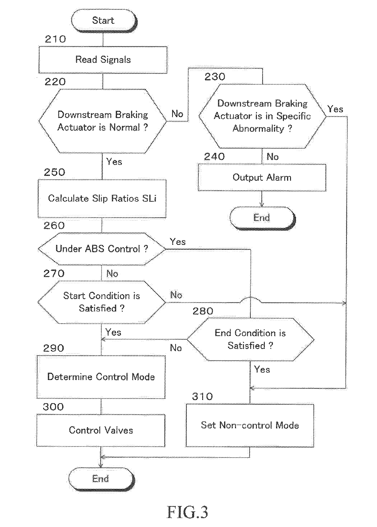
[0100]Next, the operation of the braking force control apparatus 10 according to the second embodiment will be described with respect to various cases which are in a situation where the downstream braking actuators 26A and / or 26B are in the specific abnormality. The operation of the case where the downstream braking actuators 26A and 26B are normal and the case where the downstream braking actuators 26A and / or 26B are in the other abnormality are the same as those of the first embodiment.

[0101]Affirmative determinations are made in steps 90 and 110. Therefore, in step 130, prescribed control modes of the first and second systems are determined according to the above equations (1), and the first and second upstream pressures Pu1 and Pu2 are respectively controlled in the corresponding prescribed control modes.

[0102]The prescribed control mode of the first system is set to the pressure increasing side mode out of the control modes of the left and right fr...

third embodiment

[0108]FIG. 5 is a schematic configuration diagram showing a third embodiment of the braking force control apparatus according to the present disclosure. In FIG. 5, the same reference numerals as those denoted in FIG. 1 are given to the same members as those shown in FIG. 1.

[0109]The braking force control apparatus 10 of the third embodiment and the fourth embodiment which will be described later is configured as a braking force control apparatus of X-piping two-system type including a left front wheel and right rear wheel system and a right front wheel and left rear wheel system. In the third and fourth embodiments, the left front wheel and right rear wheel system is the first system and the right front wheel and left rear wheel system is the second system, but the first and second systems may be reversed.

[0110]In the third embodiment, one end of the brake hydraulic pressure control conduit 44FR connected to the wheel cylinder 22FR of the right front wheel 18FR at the other end is c...


PUM


Abstract

A braking force control apparatus is provided which has a first system including a first upstream braking actuator and a first downstream braking actuator, a second system including a second upstream braking actuator and a second downstream braking actuator, and a control unit. When the downstream braking actuator is abnormal and the upstream pressure can be supplied to braking force generating devices, but a braking pressure of any one of the wheels cannot be normally controlled, the control unit select the pressure increasing side control mode out of the front wheel control modes as a first prescribed control mode, select the pressure decreasing side control mode out of the rear wheel control modes as a second prescribed control mode, and to control the first and second upstream pressures in the first and second prescribed control modes.

Description

CROSS-REFERENCE TO RELATED APPLICATION[0001]The disclosure of Japanese Patent Application No. JP2017-196303 filed on Oct. 6, 2017 is incorporated by reference in its entirety.BACKGROUND1. Technical Field[0002]The present disclosure relates to a braking force control apparatus for a vehicle such as an automobile.2. Description of the Related Art[0003]For example, as described in Japanese Patent Application Laid-open Publication No. 2012-116300, a braking force control apparatus having a first system for controlling braking forces of left and right front wheels, a second system for controlling braking forces of left and right rear wheels, and a control unit for controlling the first and second systems are known. The first system includes a first upstream braking actuator including a master cylinder device and generating a first upstream pressure common to the left and right front wheels and a first downstream braking actuator that individually controls braking pressures supplied to br...

Claims


Application Information

Patent Timeline
Patent Type & Authority Applications(United States)
IPC IPC(8): B60T8/28B60T8/172B60T8/176B60K28/16B60T17/22B60T13/74B60T8/26
CPCB60T8/28B60T8/172B60T8/176B60K28/16B60T17/221B60T13/745B60T8/266B60T11/34B60T13/686B60W10/184B60W20/15B60T8/17B60T8/1755B60T13/12B60T8/4872B60T8/94B60T2270/406B60T2270/413B60T13/662B60T13/146B60W30/02
Inventor KATO, HIDEHISA
Owner TOYOTA JIDOSHA KK
Why Eureka
Try Eureka