Optical flow cell assembly incorporating a replaceable transparent flow cell

a flow cell and assembly technology, applied in the direction of color/spectral property measurement, instruments, material analysis, etc., can solve the problems of phillips cell damage, inability to clean manually, and inability to remove contaminants from the cell itsel

Active Publication Date: 2019-04-11
WYATT TECH
View PDF27 Cites 16 Cited by
  • Summary
  • Abstract
  • Description
  • Claims
  • Application Information

AI Technical Summary

Problems solved by technology

A problem associated with all flow through optical cells, and in particular those which measure static light scattering, is the inevitable presence of contaminants accumulating within the cell itself.
Further, damage to the cell can occur both during manual cleaning, and albeit less frequently, during normal instrument operation.
One limitation of the Phillips cell is the difficulty associated with realignment of its optical elements after disassembly for cleaning or other maintenance.
If any of these items are in misalignment, the optical system may fail.
Further, the lack of any orienting or registration elements on the glass cell itself contributed to the possibility of misalignment due to placing the cell in 180° from its originally aligned position, as well the possibility of play in the connection elements allowing the bore to be positioned non-parallel to the optical axis defined by the position of the windows.
These limitations made realignment of the Phillips cell cumbersome every time the cell was removed from the system.
Thus, in all cases, before the present invention it was not possible to replace a flow cell with a different cell without the need to realign the system.
Of course the realignment of an optical system adds further complexity to the entire process and is generally performed only by well trained personnel, generally requiring the shipment of the entire system back to the manufacturer.

Method used


Image

  • Optical flow cell assembly incorporating a replaceable transparent flow cell
  • Optical flow cell assembly incorporating a replaceable transparent flow cell
  • Optical flow cell assembly incorporating a replaceable transparent flow cell

Examples


Embodiment Construction

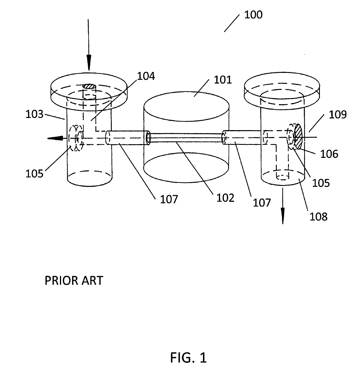
[0029]There are many instances in which the flow cell of a MALS or other light scattering instrument may need to be removed from the instrument in which it is housed. In addition to routine maintenance and cleaning, it is sometimes necessary to change the index of refraction of the cell by replacing it in order to index match the sample solvent with that of the flow cell to improve the signals received at a plurality of angles. Further, while flow cells are generally constructed from some form of glass, transparent polymers may also serve, under certain conditions, as the flow cell material, and some solvents are simply incompatible with certain flow cell materials. Therefore in order improve the versatility of a single light scattering instrument it is beneficial to enable the end user to replace the flow cell with another under these conditions. Further, as discussed previously, cleaning the flow cell itself can be a meticulous and laborious job requiring significant skill, care a...


PUM

PropertyMeasurementUnit
sizeaaaaaaaaaa
sizeaaaaaaaaaa
diameteraaaaaaaaaa

Abstract

A new liquid flow cell assembly for light scattering measurements is disclosed which utilized a floating manifold system. The assembly operates with minimal stacked tolerances by aligning the cell to the windows within a manifold and independently aligning the cell to the read head directly. This configuration enables the ability to replace the flow cell or the flow cell / manifold assembly within a light scattering instrument without the need to realign the flow through elements with the light scattering illumination source while still maintaining reproducible, quality data. Some embodiments employ wide bore cells which enable the measurement of process analytic technology (PAT) including online monitoring of reactions.

Description

RELATED APPLICATIONS AND PATENTS[0001]The following patents relate to the measurement of light scattering from a liquid sample contained in an optical flow-through cell and are hereby incorporated by reference:[0002]U.S. Pat. No. 4,616,927, S. D. Phillips, J. M. Reece, and P. J. Wyatt, “Sample cell for light scattering measurements,” issued Oct. 14, 1986.[0003]U.S. Pat. No. 4,907,884, P. J. Wyatt and S. D. Phillips, “Sample cell monitoring system,” issued Mar. 13, 1990.[0004]U.S. Pat. No. 5,404,217, G. R. Janik and J. F. Magolske, “Laser liquid flow cell manifold system and method for assembly,” issued Apr. 4, 1995.[0005]U.S. Pat. No. 6,452,672 B1, S. P. Trainoff, “Self cleaning optical flow cell,” issued Sep. 17, 2002.[0006]U.S. Pat. No. 7,982,875 B2, S. P. Trainoff, “Method and apparatus for measuring the scattered light signals from a liquid sample,” issued Jul. 19, 2011.BACKGROUND[0007]Throughout this specification, the term “particle” refers to the constituents of liquid sample...

Claims


Application Information

Patent Timeline
Patent Type & Authority Applications(United States)
IPC IPC(8): G01N21/53G01N15/14G01N21/39G01N21/05G01N30/74
CPCG01N21/532G01N15/1404G01N21/39G01N21/05G01N30/74G01N15/1434G01N2021/058G01N2030/746G01N2015/1452G01N15/0211G01N21/53G01N2021/4711G01N2021/513
Inventor RAHMLOW, DAVIDGREENSTREET, MATTHEWSEN, SHILADITYA
Owner WYATT TECH
Why Eureka
Try Eureka