
Wire-wound core, wire-wound core manufacturing method, and wire-wound-equipped electronic component

a manufacturing method and electronic component technology, applied in the direction of inductances, transformers/inductance details, inductances with magnetic cores, etc., can solve the problems of poor mass productivity, limited expansion of terminal electrode thickness, degradation of characteristics, etc., and achieve high productivity

Active Publication Date: 2019-04-18
MURATA MFG CO LTD
View PDF0 Cites 4 Cited by
  • Summary
  • Abstract
  • Description
  • Claims
  • Application Information

AI Technical Summary

Benefits of technology

This patent describes a method for manufacturing a wire-wound core, which involves winding a wire around a core portion and attaching terminal electrodes to the ends of the wire. The method is efficient and productive, even when the size of the wire-wound core decreases. The wire-wound core is also easy to assemble into an electronic component, and the reliability of its electrical connection and mechanical fixation in the mounted state is increased. The method also allows for the formation of a recessed portion with high precision, which can accommodate a conductor serving as an end surface electrode portion. The division of the mother block into smaller units increases the number of wire-wound cores that can be obtained simultaneously, leading to higher productivity and lower cost of the wire-wound cores.

Problems solved by technology

However, there is a limit in terms of increasing the thickness of the terminal electrodes.
In addition, an eddy current loss due to magnetic flux linkage increases as the thickness of the terminal electrodes increases, resulting in degradation of characteristics.
However, it is easily presumed that this method is inferior in terms of mass productivity and becomes more difficult to carry out as the size of the core decreases.
However, since end portions of the core need to be dipped separately in this case, mass productivity further decreases.

Method used


Image

  • Wire-wound core, wire-wound core manufacturing method, and wire-wound-equipped electronic component
  • Wire-wound core, wire-wound core manufacturing method, and wire-wound-equipped electronic component
  • Wire-wound core, wire-wound core manufacturing method, and wire-wound-equipped electronic component

Examples


first embodiment

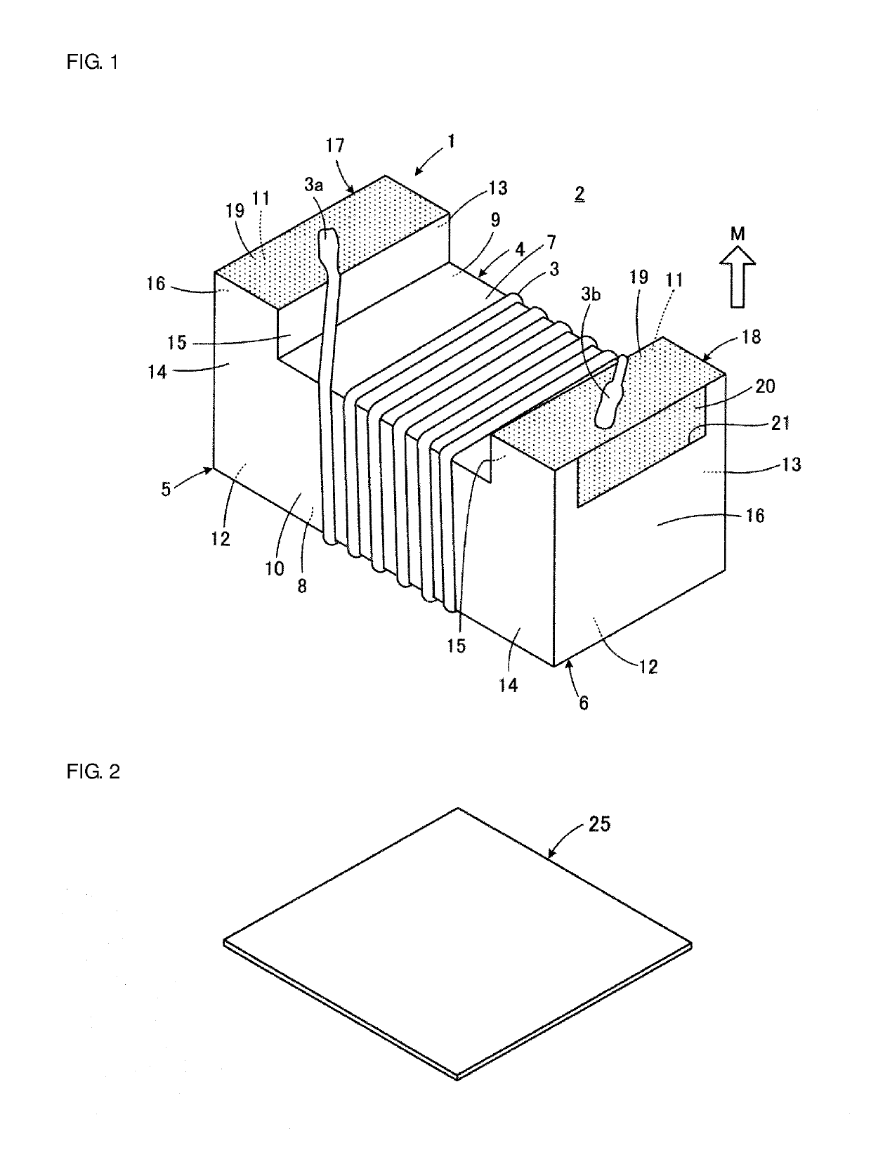
[0058]A wire-wound-equipped electronic component 2 including a wire-wound core 1 according to a first embodiment of this disclosure will be described first with reference to FIG. 1. FIG. 1 illustrates the wire-wound-equipped electronic component 2 with a bottom surface thereof to be oriented toward a mount board facing upward. The wire-wound-equipped electronic component 2 illustrated in FIG. 1 constitutes a coil component having a single coil, for example.

[0059]The wire-wound core 1 included in the wire-wound-equipped electronic component 2 includes a core portion 4 where a wound wire 3 is disposed, a first flange portion 5, a second flange portion 6, a first terminal electrode 17, and a second terminal electrode 18. The core portion 4 has a longitudinal direction. The first flange portion 5 and the second flange portion 6 are respectively located at a first end portion and a second end portion that are opposite to each other in the longitudinal direction of the core portion 4.

[006...

second embodiment

[0091]A wire-wound core 1a according to a second embodiment of this disclosure will be described next with reference to FIG. 10. In FIG. 10 and the subsequent figures, components equivalent to those illustrated in FIGS. 1 to 9 are denoted by the same or substantially the same reference signs to omit a duplicate description.

[0092]In the first embodiment described above, the core-portion top surface 8 of the wire-wound core 1 and the flange-portion top surfaces 12 are flush with each other. In contrast, in the second embodiment, the core-portion top surface 8 of the wire-wound core 1a is lower than the flange-portion top surfaces 12. That is, the core-portion top surface 8 is located closer to the mount board M than the flange-portion top surfaces 12. With such a configuration, the wound wire 3 (see FIG. 1) is successfully configured not to protrude to outside of the first flange portion 5 and the second flange portion 6 on the core-portion top surface 8 side. Thus, the wound wire 3 i...

third embodiment

[0096]A wire-wound core 1b according to a third embodiment of this disclosure will be described next with reference to FIG. 12.

[0097]In the third embodiment, the core-portion top surface 8 of the wire-wound core 1b is lower than the flange-portion top surfaces 12 as in the second embodiment described above. With this configuration, the wound wire 3 (see FIG. 1) is successfully configured not to protrude to outside of the first flange portion 5 and the second flange portion 6 on the core-portion top surface 8 side.

[0098]In the second embodiment described above, the first core-portion lateral surface 9 of the wire-wound core 1a is flush with the first flange-portion lateral surfaces 13 and the second core-portion lateral surface 10 of the wire-wound core 1a is flush with the second flange-portion lateral surfaces 14. In contrast, in the third embodiment, the first core-portion lateral surface 9 and the second core-portion lateral surface 10 of the wire-wound core 1b are lower than the...


PUM


Abstract

A wire-wound core includes a core portion extending in a longitudinal direction, first and second flange portions respectively disposed at first and second end portions of the core portion in the longitudinal direction, and at least one terminal electrode disposed at each of the first and second flange portions. When a face to be oriented toward a mount board and a face of the first flange portion facing an outer side are respectively called a bottom surface and an outer end surface, the outer end surface has a recessed portion that reaches the bottom surface. The terminal electrode disposed at the first flange portion includes a bottom surface electrode portion formed of a film conductor extending along the bottom surface of the first flange portion and an end surface electrode portion formed of a conductor filling the recessed portion and being in contact with the bottom surface electrode portion.

Description

CROSS-REFERENCE TO RELATED APPLICATION[0001]This application claims benefit of priority to Japanese Patent Application No. 2017-198306, filed Oct. 12, 2017, the entire content of which is incorporated herein by reference.BACKGROUNDTechnical Field[0002]The present disclosure relates to a wire-wound core, a wire-wound core manufacturing method, and a wire-wound-equipped electronic component including a wire-wound core and, more particularly, to improvements in a configuration of a terminal electrode disposed on the wire-wound core and in a terminal electrode formation method.Background Art[0003]For example, a technique described in Japanese Unexamined Patent Application Publication No. 2003-243226 aims to provide a wire-wound-type electronic component that makes mass production of a core easier, has small variations in inductance, and has stable fixation strength on a printed circuit board when being mounted on the printed circuit board and to provide a manufacturing method of such a ...

Claims


Application Information

Patent Timeline
IPC IPC(8): H01F27/245H01F27/28H01F27/29H01F41/02H01F27/40
CPCH01F27/245H01F27/2823H01F27/29H01F41/0233H01F27/40H01F17/04H01F41/02H01F17/045H01F27/292H01F41/0246
Inventor MORINAGA, TETSUYA
Owner MURATA MFG CO LTD
Learn More