Motor drive system including servomotor for buffer including plural windings

a technology of servomotor and buffer, which is applied in the direction of electric motor control, mechanical energy handling, dynamo-electric converter control, etc., can solve the problems of poor responsiveness of speed control of the servomotor for buffer to power discharge and power storage commands, increase in costs, and increase in size of flywheel type power storage devices. , to achieve the effect of increasing costs, increasing size and increasing the size of the flywheel type power storage devi

a technology of servomotor and buffer, which is applied in the direction of electric motor control, mechanical energy handling, dynamo-electric converter control, etc., can solve the problems of poor responsiveness of speed control of the servomotor for buffer to power discharge and power storage commands, increase in costs, and increase in size of flywheel type power storage devices. , to achieve the effect of increasing costs, increasing size and increasing the size of the flywheel type power storage devi

US20190115858A1Active Publication Date: 2019-04-18FANUC LTD

Image

  • Motor drive system including servomotor for buffer including plural windings
  • Motor drive system including servomotor for buffer including plural windings
  • Motor drive system including servomotor for buffer including plural windings

Examples


first embodiment

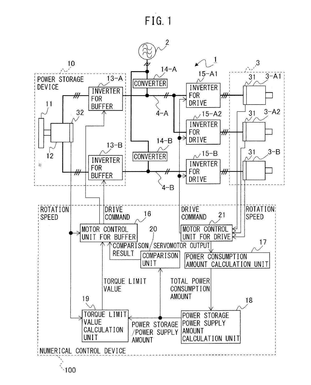
[0027]As illustrated in FIG. 1, the motor drive system 1 includes a flywheel 11, the servomotor for buffer 12, the inverters for buffer 13-A and 13-B, the converters 14-A and 14-B, the inverters for drive 15-A1, 15-A2, and 15-B, a motor control unit for buffer 16, a power consumption amount calculation unit 17, a power storage power supply amount calculation unit 18, a torque limit value calculation unit 19, and a comparison unit 20. Further, similarly to typical motor drive systems, the motor drive system 1 includes a motor control unit for drive 21 for controlling the inverters for drive 15-A1, 15-A2, and 15-B.

[0028]First, each circuit constitutional element of the motor drive system 1 according to the first embodiment will be described.

[0029]The inverters for drive 15-A1, 15-A2, and 15-B are respectively provided to the servomotors for drive 3-A1, 3-A2, and 3-B. The inverters for drive 15-A1 and 15-A2 are connected to the DC link 4-A, and the inverter for drive 15-B is connected...

second embodiment

[0103]As illustrated in FIG. 8, the motor drive system 1 includes the flywheel 11, the servomotor for buffer 12, the inverters for buffer 13-A and 13-B, the converters 14-A and 14-B, the inverters for drive 15-A1, 15-A2, and 15-B, a motor control unit for buffer 16′, the power consumption amount calculation unit 17, and the power storage power supply amount calculation unit 18. Further, similarly to typical motor drive systems, the motor drive system 1 includes the motor control unit for drive 21 for controlling the inverters for drive 15-A1, 15-A2, and 15-B.

[0104]The flywheel 11, the servomotor for buffer 12, the inverters for buffer 13-A and 13-B, the converters 14-A and 14-B, the inverters for drive 15-A1, 15-A2, and 15-B, the power consumption amount calculation unit 17, and the power storage power supply amount calculation unit 18 are similar to those in the first embodiment, and thus a detailed description of these circuit constitutional elements is omitted.

[0105]In the secon...


PUM


Abstract

A motor drive system includes: a flywheel; a servomotor for buffer which includes a plurality of independent windings and allows the flywheel to rotate; a plurality of inverters for buffer respectively connected to the windings; a plurality of converters respectively connected to the DC links; inverters for drive which perform power conversion between a DC power in the DC links and an AC power which is a drive power or a regenerative power of the servomotor for drive; and a motor control unit for buffer configured to control driving of the servomotor for buffer by controlling power conversion of the respective inverters for buffer respectively connected to the windings.

Description

BACKGROUND OF THE INVENTION1. Field of the Invention[0001]The present invention relates to a motor drive system including a servomotor for buffer including a plurality of windings.2. Description of the Related Art[0002]In a motor drive system for driving a servomotor provided to machines including a machine tool, a robot, etc., (hereinafter referred to as “servomotor for drive), an AC power supplied from a power supply is converted by a converter (rectifier) to a DC power so as to be outputted to a DC link, further, the DC power of the DC link is converted by an inverter to an AC power, and the AC power is used as a power for driving the servomotor for drive provided to each drive axis. Typically, one converter is provided to a plurality of inverters for the purpose of reducing costs of the motor drive system or a space occupied. In other words, the converter for converting an AC power supplied from the AC power supply to a DC power is configured to be a power supply unit common to ...

Claims


Application Information

Patent Timeline
18 Apr 2019
Publication
US20190115858A1
IPC
H02P11/04; H02K7/02; H02P27/08
CPC
H02P11/04; H02K7/025; H02P27/08; H02P2201/03; H02P2205/03; H02P2205/05; H02P5/74; H02P23/04
Inventors
SHINODA, SHOUGO; IKAI, SATOSHI