
Power amplifying device

a power amplifier and amplifier technology, applied in the direction of high-frequency amplifiers, amplifier modifications to reduce non-linear distortion, one amplifier with multiple channels, etc., can solve problems such as deterioration of distortion characteristics

Active Publication Date: 2019-04-18
SAMSUNG ELECTRO MECHANICS CO LTD
View PDF1 Cites 0 Cited by
  • Summary
  • Abstract
  • Description
  • Claims
  • Application Information

AI Technical Summary

Benefits of technology

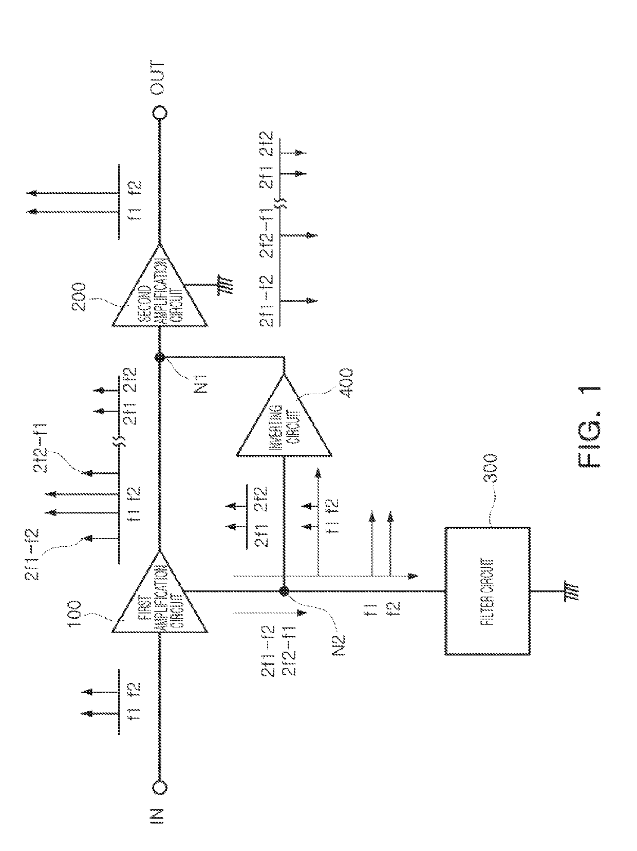
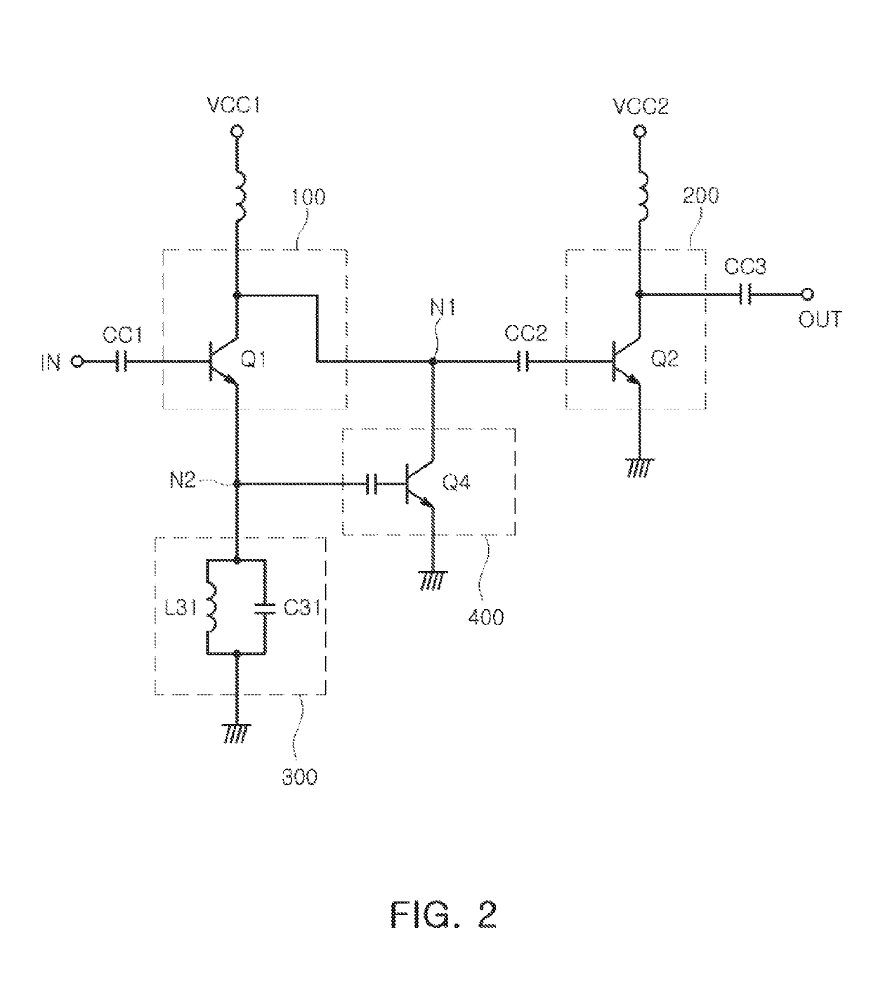
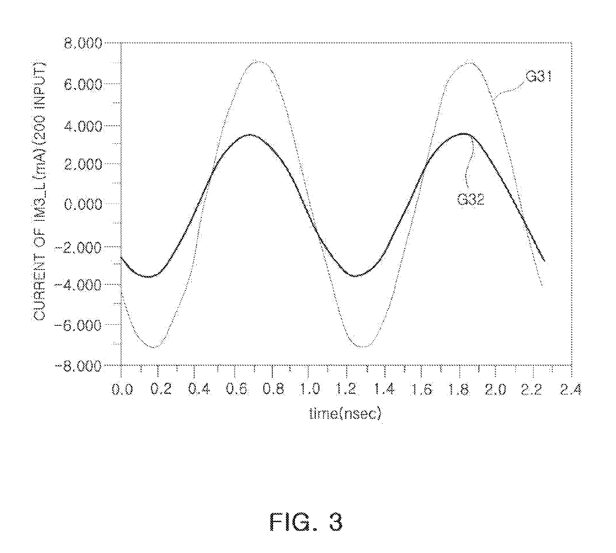
The patent describes a power amplifying device that includes two amplification circuits and a filter circuit. The filter circuit passes the first and second signals through a common ground node, and an inverting circuit is connected to the output of the first amplification circuit. The inverting circuit phase-inverts the signals and provides them to the output of the first amplification circuit. The device also includes a resonance circuit with inductor and capacitor elements to generate impedance with low and high impedance components for the first and second signals. The technical effects of the device include improved amplification of signals with reduced intermodulation distortion and improved filtering of signals.

Problems solved by technology

However, according to the typical RF power amplifier, in a case in which an interval between fundamental frequency components of two or more different bands is relatively narrow, since a third-order intermodulation distortion (IM3) component and a second harmonic component due to different frequency components are adjacent to the fundamental frequency component, there is a problem in that distortion characteristics may be deteriorated.

Method used


Image

  • Power amplifying device
  • Power amplifying device
  • Power amplifying device

Examples


Embodiment Construction

[0035]The following detailed description is provided to assist the reader in gaining a comprehensive understanding of the methods, apparatuses, and / or systems described herein. However, various changes, modifications, and equivalents of the methods, apparatuses, and / or systems described herein will be apparent after an understanding of the disclosure of this application. For example, the sequences of operations described herein are merely examples, and are not limited to those set forth herein, but may be changed as will be apparent after an understanding of the disclosure of this application, with the exception of operations necessarily occurring in a certain order. Also, descriptions of features that are known in the art may be omitted for increased clarity and conciseness.

[0036]The features described herein may be embodied in different forms, and are not to be construed as being limited to the examples described herein. Rather, the examples described herein have been provided mer...


PUM


Abstract

A power amplifying device includes a first amplification circuit amplifying a first signal having a first frequency component and a second frequency component; a second amplification circuit amplifying a second signal received through an output node of the first amplification circuit; a filter circuit connected between a ground node of the first amplification circuit and a common ground to pass the first and second frequency components to the common ground through the ground node; and an inverting circuit that phase-inverts a signal including second harmonic components of the first and second frequency components that are received through the ground node of the first amplification circuit and provide the phase inverted signal to the output node of the first amplification circuit.

Description

CROSS-REFERENCE TO RELATED APPLICATION(S)[0001]This application claims the benefit under 35 USC 119(a) of Korean Patent Application No. 10-2017-0134508 filed on Oct. 17, 2017 in the Korean Intellectual Property Office, the entire disclosure of which is incorporated herein by reference for all purposes.BACKGROUND1. Field[0002]The present disclosure relates to a power amplifying device such as a power amplifier device.2. Description of Related Art[0003]In general, as the demand for broadband, multimedia and smart technology in wireless communication systems gradually increases, broadband, improvements in linearity, and the implementation of smart technology in radio frequency (RF) power amplifiers (PA) applied to the wireless communications system has increased.[0004]Since RF power amplifiers are required to operate linearly in a higher power region, linearity should be ensured without distortion for wideband signals including a plurality of frequency bands.[0005]However, according to...

Claims


Application Information

Patent Timeline
IPC IPC(8): H03F3/21H03F1/56H03F1/32H03F3/19
CPCH03F3/211H03F1/56H03F1/32H03F3/19H03F2203/21139H03F2203/21169H03F2200/451H03F2203/21157H03F2201/3206H03F2200/111H03F2200/171H03F2200/267H03F2200/336H03F2200/399H03F1/3223H03F1/565H03F2201/3212
Inventor CHOI, KYU JIN
Owner SAMSUNG ELECTRO MECHANICS CO LTD
Learn More