Transapically-implanted mitral valve flexible coaptation plate blocking body and implantation method

Active Publication Date: 2019-04-25
SHANGHAI JOY MEDICAL DEVICES CO LTD
View PDF3 Cites 1 Cited by
  • Summary
  • Abstract
  • Description
  • Claims
  • Application Information

AI Technical Summary

Benefits of technology

[0016]With the above technical solution adopted by the present invention, there are the following advantages: the flexible closure plate in the mitral valve flexible closure plate blocking body of the present invention is made from a flexible material with excellent ductility, is implanted via a small incision on the left side of the chest, enters the left ventricle via the cardiac apex, and is placed and fixed at a regurgitation hole position of the anterior and posterior leaflet commissures of the mitral valve. During diastoles, the mitral valve opens, and blood flows from the left atrium to the left ventricle via two channels between the anterior and posterior leaflets and the closure plate. During systoles, t

Problems solved by technology

Mitral valve regurgitation will cause pulmonary congestion and left ventricular 3 hypertrophy, which ultimately leads to heart failure and death of patients.
Such flow-back is called mitral valve regurgitation, which reduces heart efficiency and causes heart failure.
At present, for the treatment of mitral valve regurgitati

Method used


Image

  • Transapically-implanted mitral valve flexible coaptation plate blocking body and implantation method
  • Transapically-implanted mitral valve flexible coaptation plate blocking body and implantation method
  • Transapically-implanted mitral valve flexible coaptation plate blocking body and implantation method

Examples


Embodiment Construction

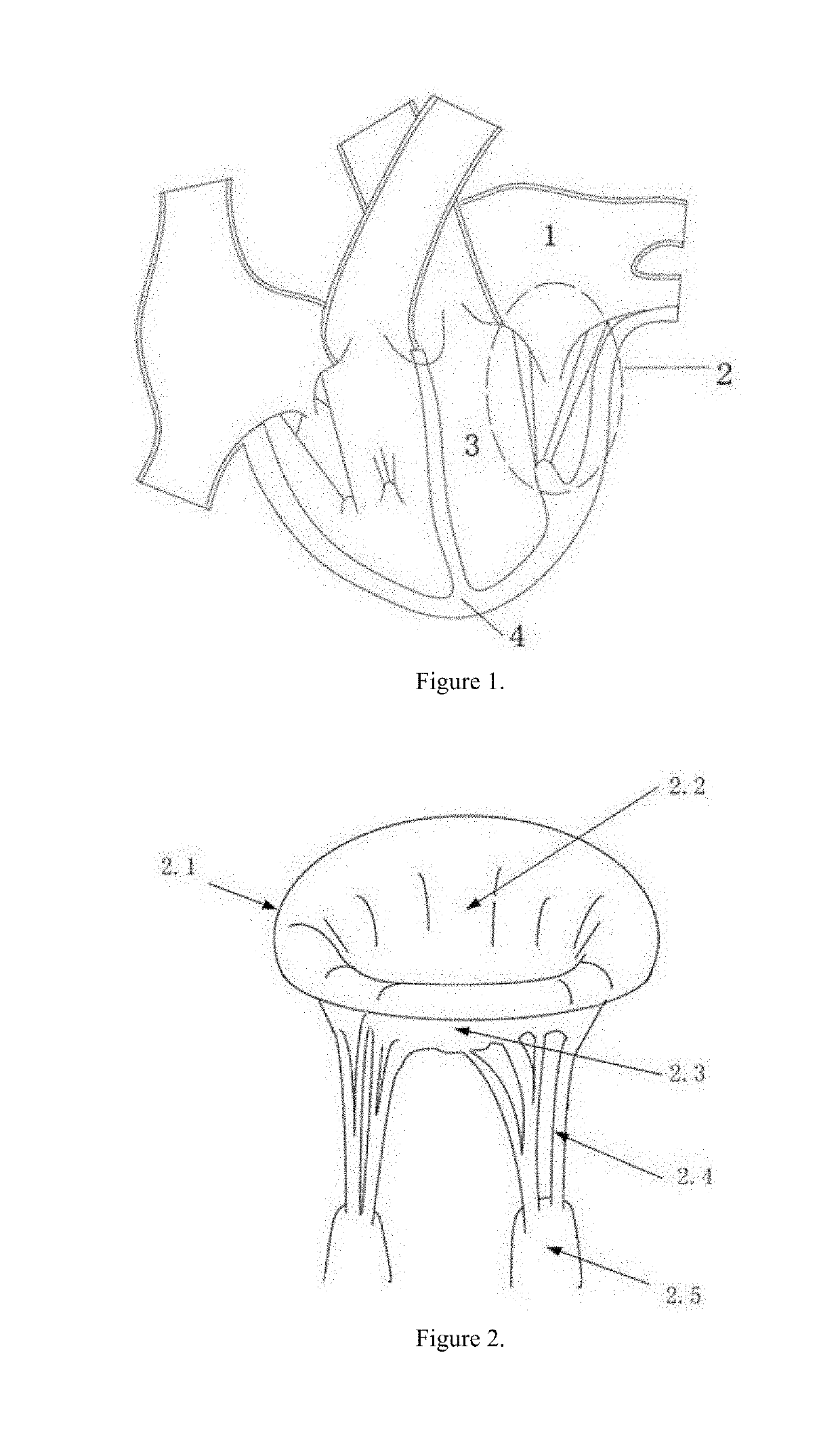
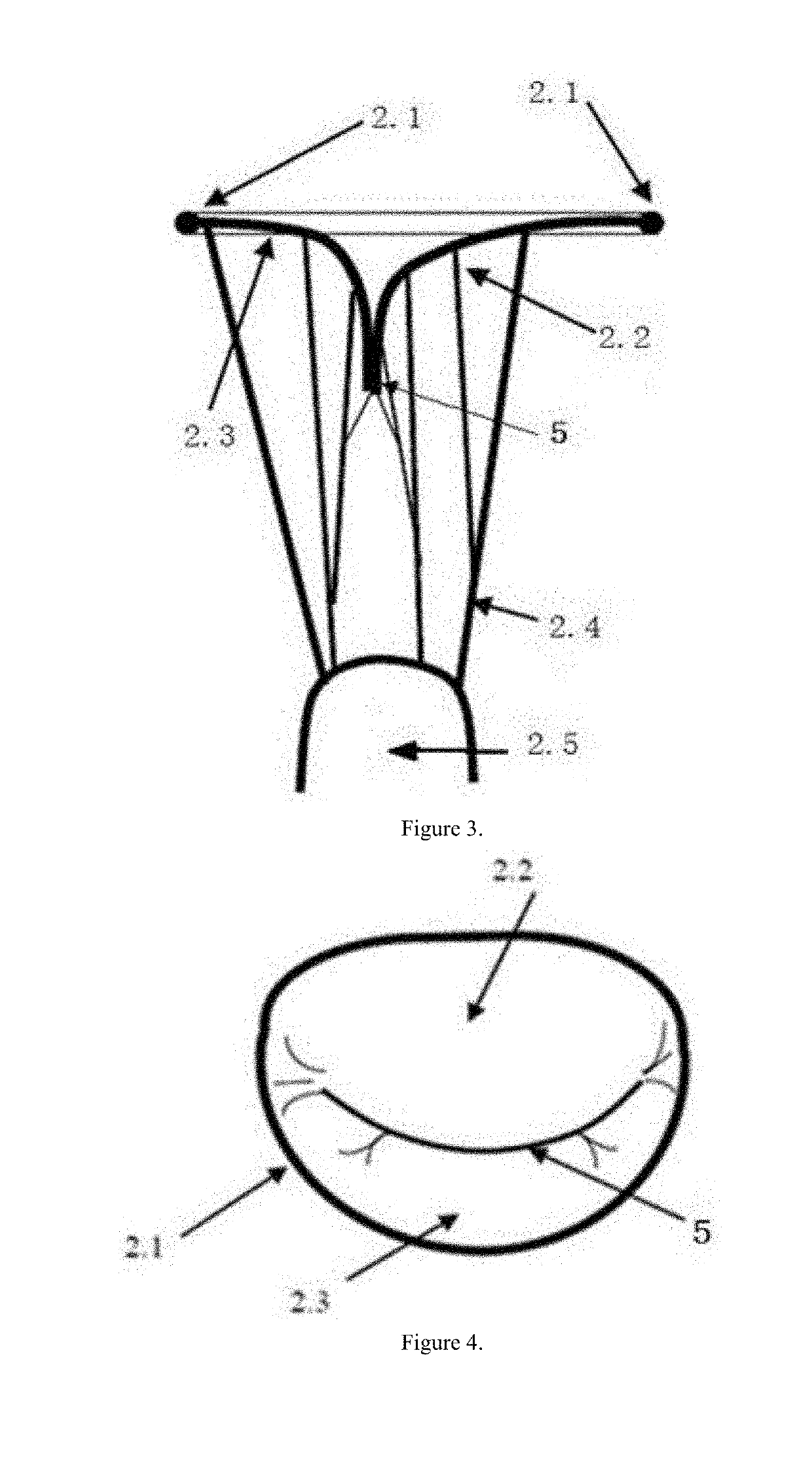
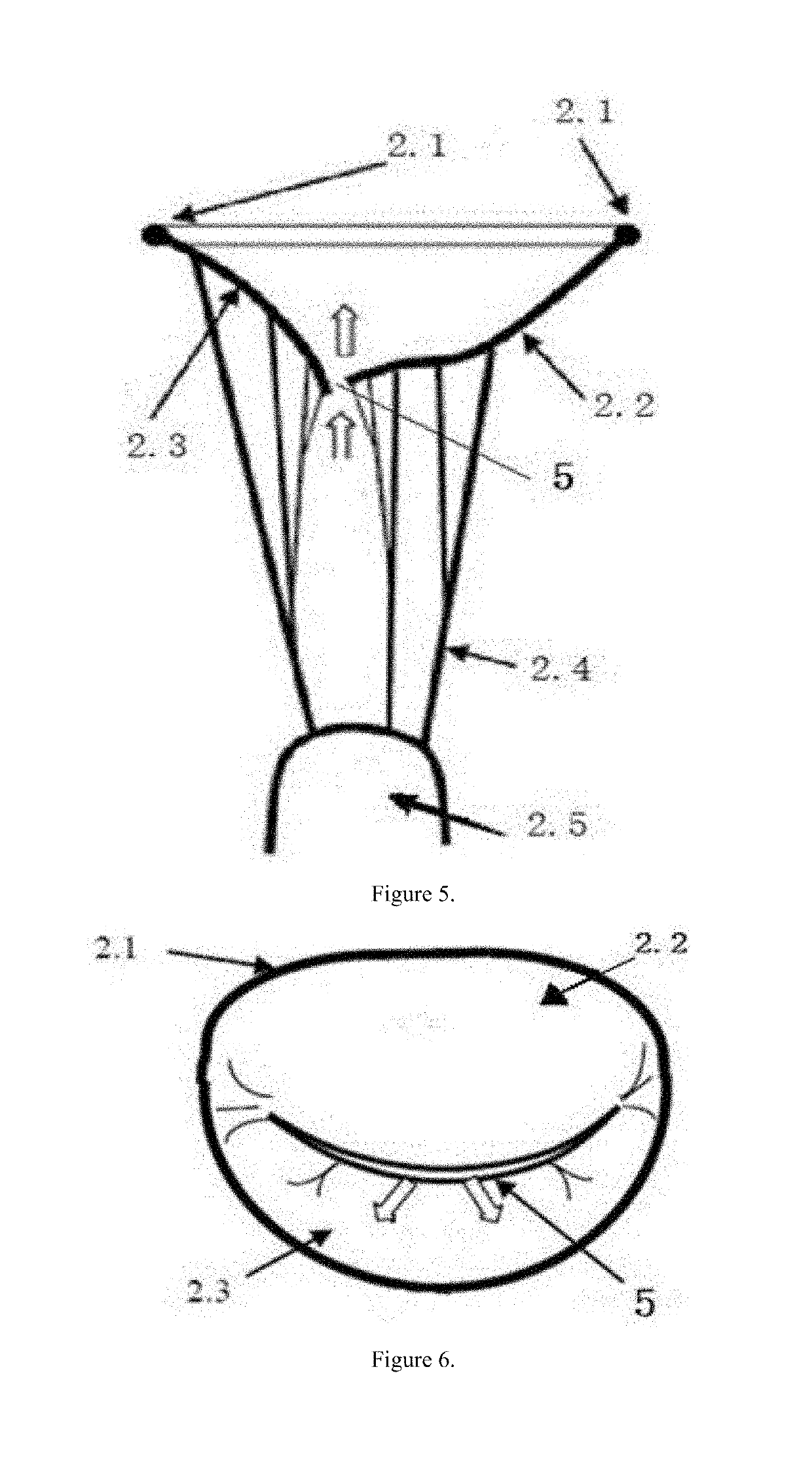
[0029]Referring to FIG. 7, the structure of a transapically-implanted mitral valve flexible closure plate blocking body comprises a hook 6, a flexible closure plate 7, a guide wire 8, a pull wire 10, a guide ring 13, a support rod 14 and a fixation plug 12. The fixation plug 12 is implanted at a cardiac apex 4. There are two hooks 6, which are implanted in the left and right positions on a mitral valve annulus 2.1 at an anterior-posterior leaflet junction 5, respectively. The flexible closure plate 7 is made from a flexible material with excellent ductility. The longitudinal section thereof has an inverted isosceles trapezoidal structure with a front and rear thickness of 5-6 mm. The length of the upper base of the isosceles trapezoid is longer than that of the lower base. The flexible closure plate 7 is capable of being tightly crimped into an elongated cylinder along their mutually parallel upper or lower base edges. The flexible closure plate 7 is placed between the anterior and ...


PUM


Abstract

Disclosed are a transapically-implanted mitral valve flexible closure plate blocking body and an implantation method which belong to the technical field of human heart repair. A flexible closure plate (7) is implanted via a small incision on the left side of the chest, enters the left ventricle (3) via the cardiac apex (4), and is placed and fixed at a regurgitation gap position of the anterior and posterior leaflet junction (5) of the mitral valve (2). During diastoles, the mitral valve (2) opens, and blood flows from the left atrium (1) to the left ventricle (3) via two channels between the anterior and posterior leaflets (2.2, 2.3) and the closure plate (7). During systoles, the anterior and posterior leaflets (2.2, 2.3) close, the edges of the leaflets squeeze the closure plate (7) so that the plate deforms slightly, and the edges of the leaflets and the slightly deformed closure plate (7) are tightly bound together, thereby blocking a regurgitation gap of the mitral valve (2), and effectively preventing regurgitation of the mitral valve (2). The flexible closure plate blocking body is simple in structure and highly reliable, the implantation method thereof causes little trauma of the body, and the residual regurgitation rate is low. The present invention treats diseases such as functional mitral valve insufficiency, and the success rate for repairing functional mitral valve regurgitation is more than 90%.

Description

TECHNICAL FIELD[0001]The present invention relates to the field of human heart repair technology and medical instruments, in particular to an instrument capable of repairing mitral valve regurgitation of the heart.BACKGROUND ART[0002]The human heart and valve are shown in FIG. 1. The left ventricle 3 is located at the upper left of the cardiac apex 4, the mitral valve 2 is located between the left atrium 1 and the left ventricle 3, and the mitral valve 2 controls the unidirectional flow of blood from the left atrium 1 into the left ventricle 3. The dysfunctional mitral valve 2 may cause the two leaflets of the mitral valve 2 to be incompletely closed, causing the blood to flow back from the left ventricle 3 to the left atrium during systoles. Mitral valve regurgitation will cause pulmonary congestion and left ventricular 3 hypertrophy, which ultimately leads to heart failure and death of patients.[0003]The structure of the mitral valve 2 is shown in FIG. 2. The mitral valve 2 is a c...

Claims


Application Information

Patent Timeline
IPC IPC(8): A61F2/24
CPCA61F2/246A61F2/2418A61F2/2445A61F2220/0025A61F2210/0014A61B17/0057A61B2017/00623A61B2017/00592A61B2017/00579A61F2/24A61B17/00A61F2/2454A61F2/2487A61F2220/0083
Inventor HE, ZHAOMINGJING, TENGZHANG, KAILIANG
Owner SHANGHAI JOY MEDICAL DEVICES CO LTD
Why Eureka
Try Eureka