During the movement of the platform caused by an operator at the platform control desk, there is a risk that the operator may be crushed against the desk by an external obstacle—for example a part of a building, a structure or a tree
branch—striking him from behind or from above.
The same risk may exist with respect to the guardrail in the case where the operator may stand alongside the desk while manipulating the control members thereof.
One drawback of this type of solution relates to the fact that the operator may in normal times exert high forces on the desk, for example by holding onto the control members in order to avoid being unbalanced by the movements of the platform.
Consequently crushing is detected only if the force of crushing the operator against the desk is very high, who thereby risks being injured.
Moreover, it does not provide protection of the operator vis-a-vis the risk of crushing against the guardrail when he is standing alongside the desk instead in front of it.
Finally, this type of solution is designed for fixed desks: it is completely unsuitable for desks that can be moved by the operator.
However, it has all the other drawbacks of the previous solution.
Furthermore, the device for protection against crushing is liable to be triggered in an unwanted fashion in the case where
heavy equipment is placed against this guardrail section.
Finally, this solution is difficult to implement when the platform has parts that are extensible at the ends of its
deck in order to vary the length thereof.
The drawback of these solutions is procuring protection against crushing from above, rather than from the side.
In addition, protection against crushing from above is not reliable in the case where the aerial work platform is used under roofs or structures where beams intersect.
Moreover, the rods or the projecting frame interfere with the handling of the equipment
on board the platform and are exposed to impacts during such handling.
Finally, it is difficult to adapt such rods or such a frame to a foldable guardrail that can be folded onto the
deck of the work platform.
This solution is very bulky and interferes with handling of the equipment
on board the platform, and the protection device is liable to trigger in an unwanted fashion if equipment is placed on or against the guardrail, and therefore against this double frame.
This solution has the drawback that the uprights interfere with the freedom of movement of the operator and are exposed to impacts when equipment
on board the platform is handled.
In addition, the device for protection against crushing is liable to trigger in an unwanted fashion when large items of equipment such as battens or props are placed against or on the guardrail.
Moreover, this solution requires precise mutual positioning of the distant emitters and receivers which is difficult to maintain during use of the aerial work platform because of the variable deformation of the deck of the work platform depending on the load placed on the deck and its location thereon.
In addition, this requirement for precise mutual positioning of the emitters and receivers makes this solution incompatible with work platforms having one or two parts extensible at the ends of their deck in order to vary the length because of the relative clearances allowing sliding between these extensible parts and the deck.
The safety bar may interfere with the freedom of movement of the operator and is generally exposed to impacts when the persons on board the platform
handle equipment, in particular if it is large, such as battens or props.
It also does not provide protection for the operator vis-a-vis the risk of crushing against the guardrail when he is standing alongside the desk instead in front of it.
Finally, this type of solution is designed for fixed desks and is difficult to apply to, or even completely unsuitable for, desks that can be moved by the operator because of their compactness and their removable mounting on the guardrail, which does not provide a sufficiently firm holding on the guardrail.
If the operator is pushed towards the desk by an external obstacle, his body cuts one or other or both of the light beams, in which case the corresponding
receiver or receivers no longer receive the light of the corresponding beam and consequently the device stops the movement of the aerial work platform.
This solution has drawbacks similar to those of the detection bars because of the arms supporting the emitters and receivers.
This is because these arms interfere with the freedom of movement of the operator and are exposed to impacts when equipment is being manipulated on board the platform.
It also does not provide protection of the operator vis-a-vis the risk of crushing against the guardrail when he is standing alongside the desk instead of in front of it.
In addition, manipulating the control members of the desk from the standing position alongside the desk is difficult because of the arms and the risk of accidental interference with the top
light beam, whereas this possibility may be desirable.
Moreover, this solution is unsuited to the case where provision is made for the operator to stand alongside the desk rather than in front of it in order to manipulate the control members.
It is also not suited to the case where the desk is attached removably to the guardrail in order to be able to be moved by the operator.
In the latter case, it could be envisaged mounting the arms supporting the emitters and receivers directly on the sides of the desk, but the aforementioned drawbacks remain because of the projection of the arms towards the front and above the desk.
These drawbacks would also be increased in the case of a small desk designed both to be attached removably to the guardrail and to be held with one hand while its control members are manipulated with the other hand.
More particularly, the presence of the operator in front of the desk is detected by the fact that the
ultrasound receiver receives
ultrasound emitted by the
ultrasound emitter because of its reflection on the operator, which is not the case when the operator is not standing in front of the desk.
The cord is liable to be pulled away and damaged when equipment is manipulated on board the platform, in particular if it is large.
Further, it interferes with the use of the platform where it is normal for persons on board to place large equipment, such as battens or props, against the guardrail.
Finally, this solution is completely unsuited to the case of movable desks.
According to yet another solution, GB 2 495 158 A teaches equipping the platform with proximity sensors on the top of the guardrail in order to detect the proximity of obstacles external to the platform, for example at distances of 5 m, 3 m or 2 m. This solution is however unusable for work in an environment at a height that is very encumbered, such as under roofs or structures where beams intersect.
In addition, the sensors may be damaged when equipment is handled on board the platform or the device may be triggered in an unwanted fashion when equipment—such as battens or props—is placed against or on the guardrail.
This solution has the drawback of requiring
electronics for real-
time processing of the signals from the camera, which is complex and also cannot be used for work in a very encumbered environment at a height.
The risk of unwanted triggering of the security device is also possible when equipment is placed against or on the guardrail.
In particular, the
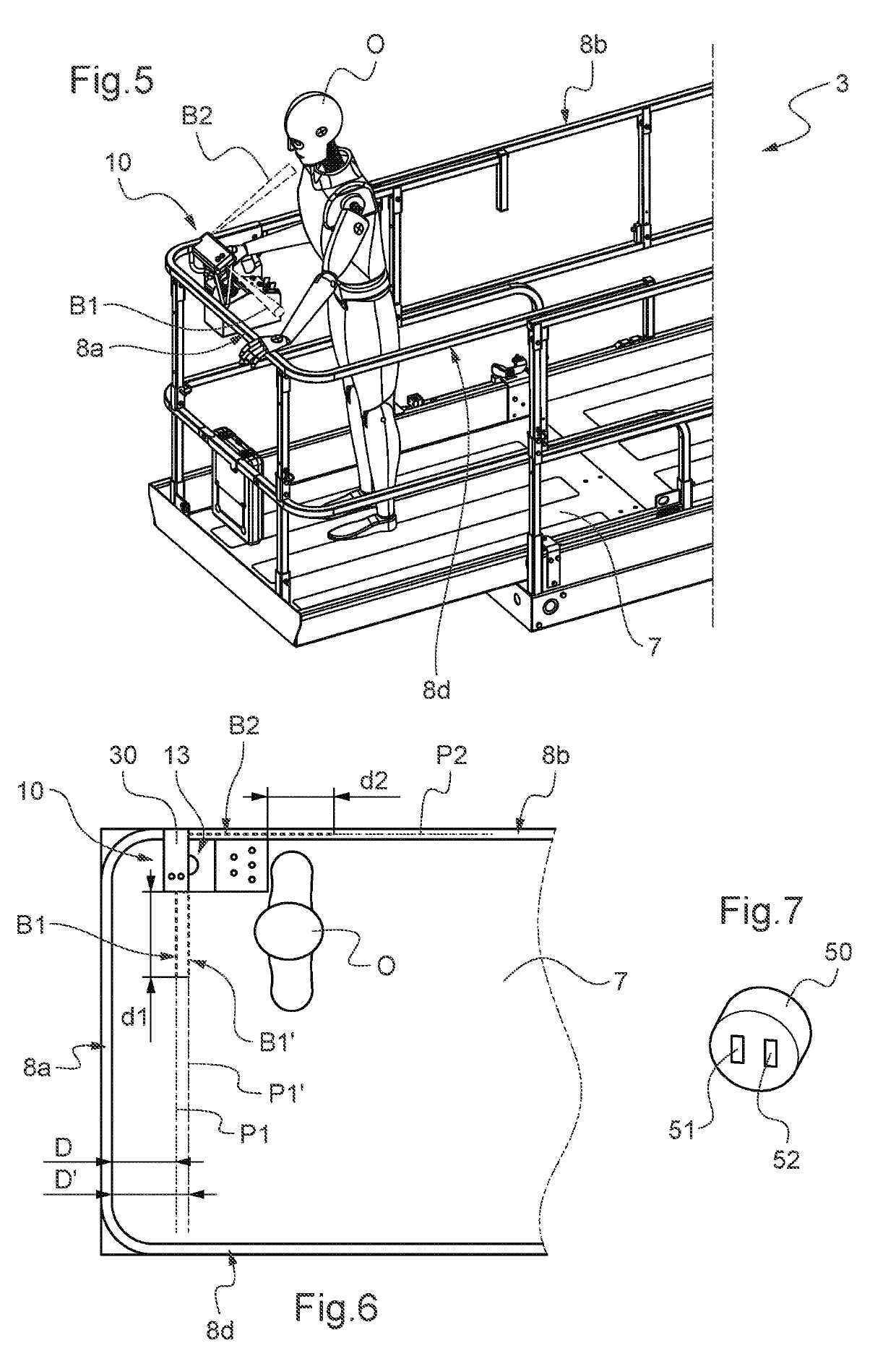
sizing thereof can be limited so as to protect the operator from crushing against the desk and / or guardrail only when he is in a position in front of and / or alongside the desk from which he is in a position to manipulate the control members of the desk.

