Transport system, processing system, and article manufacturing method

Active Publication Date: 2019-05-02
CANON KK
View PDF0 Cites 8 Cited by
  • Summary
  • Abstract
  • Description
  • Claims
  • Application Information

AI Technical Summary

Benefits of technology

[0009]An aspect of the present disclosure provides a transport system capable of precise positioning while su

Problems solved by technology

In Japanese Patent Laid-Open No. 2005-269822, however, the permanent magnet of the transport carriage is arranged between two guide rails that are arranged, and when the center axis of the space between the guide rails is deviated, it is concerned that the transport carriage is deformed due to an attractive force.
Though rigidity of the transport carriage needs to be increased to suppress the deformation, an adverse effect, for example, that the transport carriage becomes heavy due to the increased rigidity and more thrusts are required is cau

Method used


Image

  • Transport system, processing system, and article manufacturing method
  • Transport system, processing system, and article manufacturing method
  • Transport system, processing system, and article manufacturing method

Examples


first embodiment

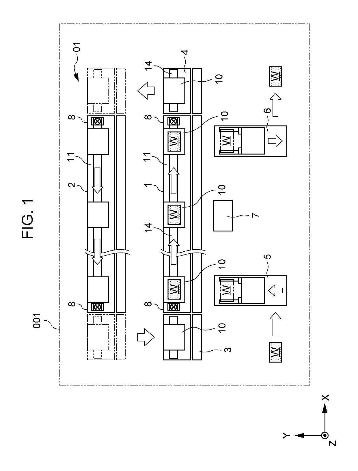
[0036]Next, with reference to FIGS. 2, 3, and 4A to 4C, a first embodiment will be schematically described with configurations of the transport apparatus outward path 1, the transport apparatus homeward path 2, the carriage transfer apparatuses 3 and 4, and the transport carriage 10 in the transport system 01.

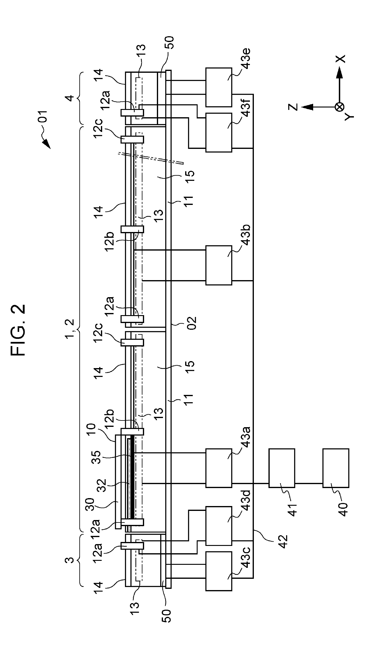
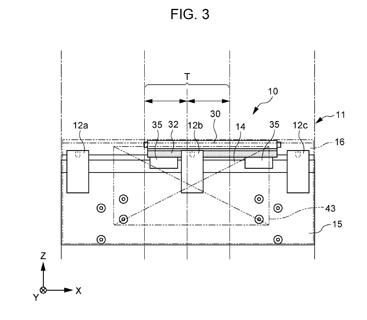
[0037]FIG. 2 illustrates the transport apparatus outward path 1 as viewed from the Y direction. FIG. 3 illustrates the transport carriage 10 and the transport modules 11 serving as a part of the transport path, as viewed from the Y direction. FIGS. 4A to 4C are sectional views illustrating configurations of the transport carriage 10 and the transport module 11.

[0038]The transport apparatus outward path 1 is configured to be modularized and has the plurality of transport modules 11. The processing system 001 has a plurality of lower controllers 43 that are connected to the plurality of transport modules 11, the carriage transfer apparatus 3, and the carriage transfer apparatus 4...

second embodiment

[0062]FIG. 5 is a sectional view illustrating configurations of the transport carriage 10 and the transport module 11 according to a second embodiment. A member having the same configuration as that of the first embodiment will be given the same reference sign and description thereof will be omitted. In the first embodiment, an example that the guide block 35, the carriage driving coil 13, and the permanent magnet 33 fall within the range (E) of the width of the guide rail 14 are installed so that the respective X-Z virtual planes thereof fall within the range (E) of the width of the guide rail 14 and the Z direction of each of the X-Z virtual planes faces a gravitational direction is indicated. In the present embodiment, indicated is an example that the guide block 35, the carriage driving coil 13, and the permanent magnet 33 are installed in the same manner so that respective virtual planes thereof fall within the range (E) of the width of the guide rail 14, however, in a case whe...

third embodiment

[0067]Next, an example of a transport apparatus capable of detecting a correct position even when a housing is deformed due to thermal expansion of a carriage driving coil will be described as a third embodiment. A member having the same configuration as those of the first and second embodiments will be given the same reference sign and description thereof will be omitted. First, thermal expansion of the transport module 11 explained in FIGS. 2, 3, and 4A to 4C will be specifically described with reference to FIGS. 6A and 6B.

[0068]FIG. 6A illustrates thermal expansion of the transport module housing 15 of the transport module 11 in the third embodiment.

[0069]The carriage driving coil 13 (not illustrated) generates heat by energization to operate the transport carriage 10. By continuously operating the transport carriage 10, the heat of the carriage driving coil 13 is transmitted to the stand 02 through the transport module housing 15 or radiated to the peripheral air contacting the ...


PUM


Abstract

In a transport system that moves a moving portion, which moves in a transport direction along a fixed portion, while detecting a position of the moving portion by a scale and a sensor, a guide block is installed on a second surface of a first part of the moving portion, a guide rail is installed on a first surface of the fixed portion, the scale is installed at an end of the first part of the moving portion on an opposite side across the guide block, and a sensor that has a detecting unit at a position facing the scale is installed in the fixed portion.

Description

BACKGROUNDField[0001]The present disclosure relates to a transport apparatus that uses a linear motor used for driving or the like of a slider of a transport apparatus for factory automation (FA), a processing system, and an article manufacturing method.Description of the Related Art[0002]In general, in a factory-automated production line for assembling an industrial product, a transport apparatus that transports a workpiece, a part, or the like is used. Conventionally, there has been a production line in which a large amount of parts each having many complicated shapes and structures, for example, such as a camera or a printer cartridge, are assembled in an assembly line system. Assembling apparatuses that are adjacent are connected to each other by a transport portion, and a workpiece that is a target to be assembled is successively caused to face the respective apparatuses to perform processing continuously. The workpiece transferred from the transport portion is positioned by a ...

Claims


Application Information

Patent Timeline
IPC IPC(8): H02K41/03B65G47/74B23Q7/14
CPCH02K41/031B65G47/74B23Q7/14B65G2203/042B65G37/02B65G54/02
Inventor SUZUKI, HITOSHIYAMAMOTO, TAKESHITOE, YUUYAOKAZAKI, RYOTAHIROKAWA, KICHINOSUKE
Owner CANON KK
Why Eureka
Try Eureka