
System for controlling ablation treatment and visualization

a technology of ablation treatment and visualization, applied in the field of medical device control mechanisms, can solve the problems of confusing results and treatments, crowded operating theater, etc., and achieve the effect of facilitating the sizing of the treatment area and minimizing the ablation of the tissue region surrounding

Active Publication Date: 2019-05-09
ACESSA HEALTH INC
View PDF1 Cites 6 Cited by
  • Summary
  • Abstract
  • Description
  • Claims
  • Application Information

AI Technical Summary

Benefits of technology

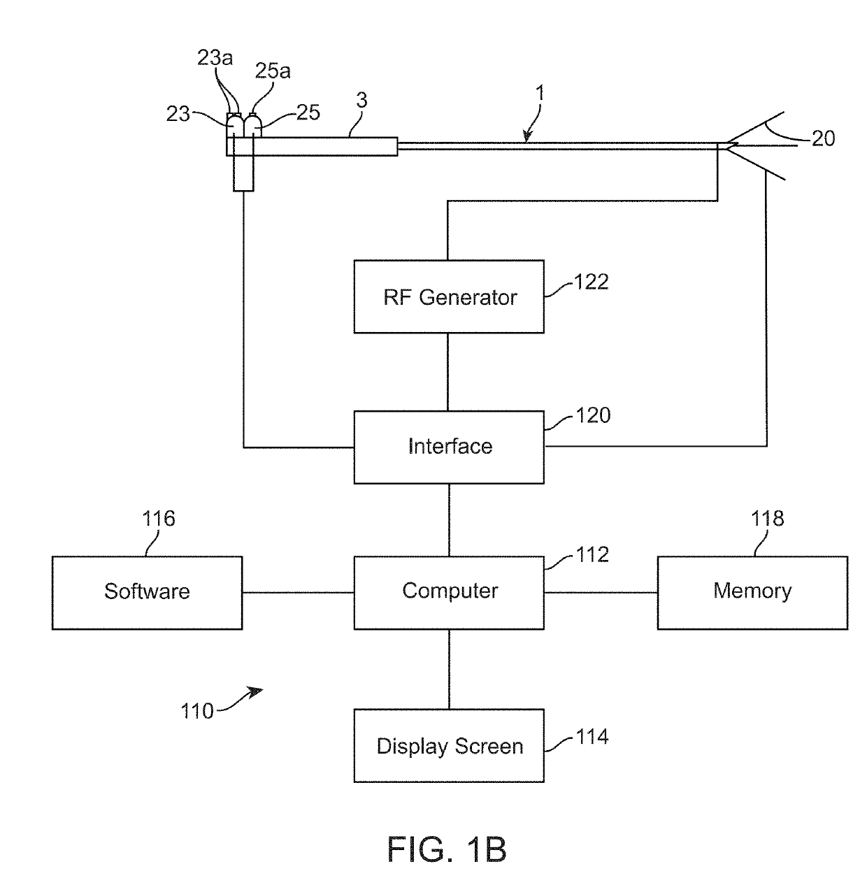
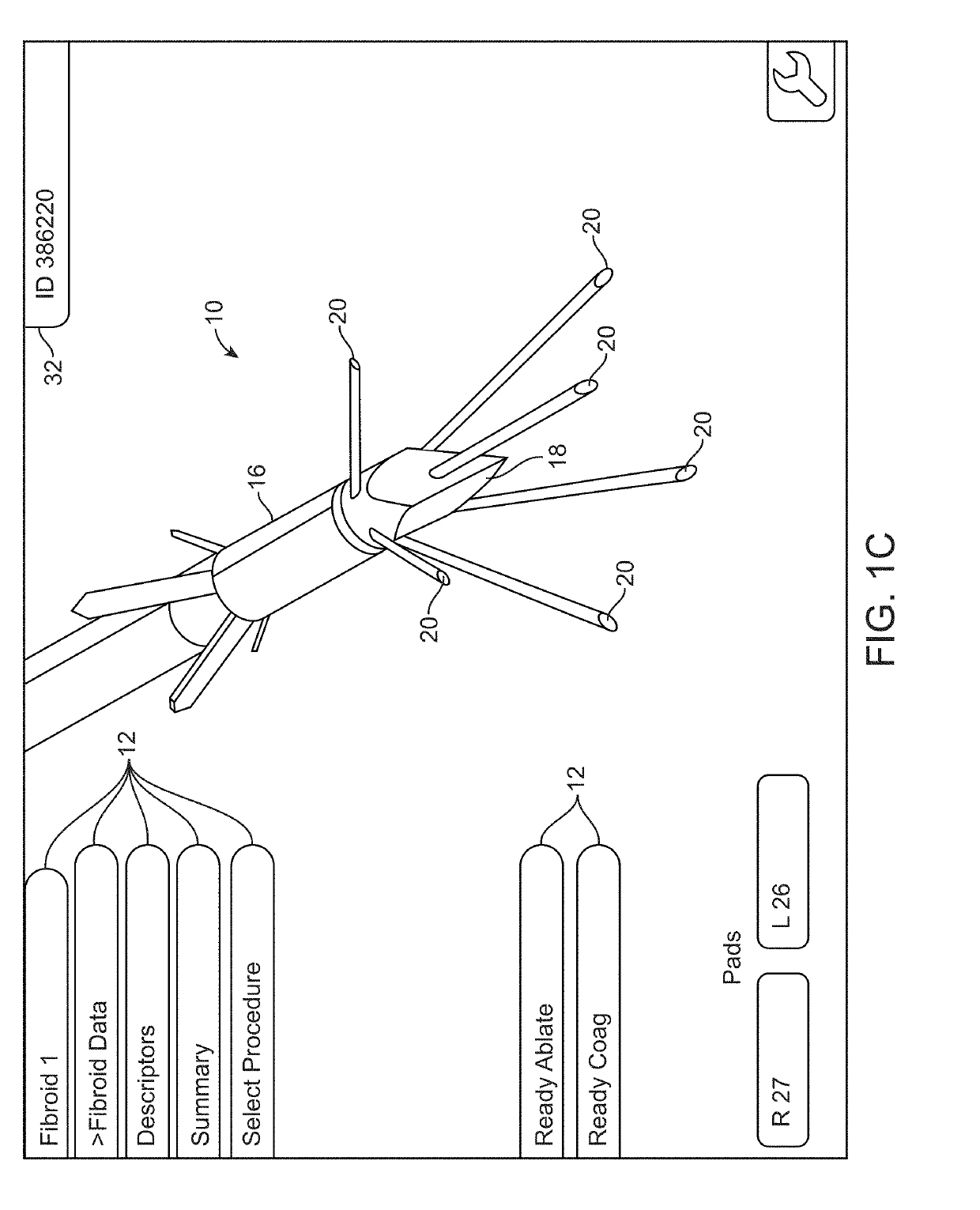
The patent describes a new system for guiding the placement of an ablation device to treat medical conditions such as fibroids. The system includes an RF ablation component, an ultrasound machine, and a guidance mapping system. The ultrasound machine can help position the ablation device, and the guidance mapping system can help the surgeon understand the placement of the device in real-time. The system is designed to be easy to use and configure, and it allows for seamless integration of different components. The user can adjust the size of the treatment area by adjusting the length of the ablation device's stylets, and a visual representation of the ablation zone can be generated based on specified parameters. The technical effects of this system are improved visual guidance, simplified use, and better outcomes in treating medical conditions with ablation therapy.

Problems solved by technology

However, such systems typically require the user of multiple components which are separate from one another which may present multiple sources of information in a disparate manner.
For instance, imaging systems, navigational mapping systems, tissue ablation systems, etc. may each require its own equipment and attention in utilizing the device and may also present a crowded operating theater.
This may lead to confusing results and treatments.

Method used


Image

  • System for controlling ablation treatment and visualization
  • System for controlling ablation treatment and visualization
  • System for controlling ablation treatment and visualization

Examples


Embodiment Construction

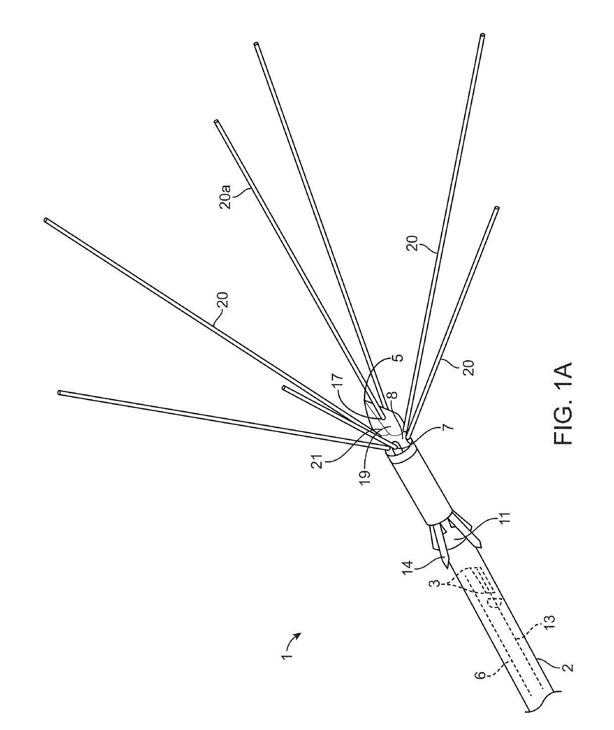
[0048]FIG. 1A is a perspective view of a multiple antennae or stylet ablation trocar instrument 1 useful in practicing the inventive system. Ablation instrument 1 comprises a cannula 2 which houses a plurality of stylets 20 and, optionally, a plurality of anchors 4. A trocar point 5 is provided at the distal end of cannula 2. At least one conductor 6 is provided within cannula 2. Conductor 6 is electrically coupled to stylets 20 and trocar point 4 and accordingly provides RF energy to stylets 20 and trocar point 5. In accordance with the invention, stylets 20 and trocar point 5 are electrically coupled to each other and electrically isolated from other exposed portions of ablation instrument 1. Stylets 20 and trocar point 5 are at the distal end of ablation instrument 1. Each of the stylets is made of thin wire-like tubular members and during the procedure is initially housed entirely within the cannula 2. In other variations, the stylets 20 and trocar point 5 may instead be configu...


PUM


Abstract

A system for controlling ablation treatment and visualization is disclosed where the system comprises a tissue ablation instrument having one or more deployable stylets and a first electromagnetic sensor and an ultrasound imaging instrument which may be configured to generate an ultrasound imaging plane and further having a second electromagnetic sensor. An electromagnetic field generator may also be included which is configured for placement in proximity to a patient body and which is further configured to generate an output indicative of a position the first and second electromagnetic sensors relative to one another. Also included is a console in communication with the ablation instrument, ultrasound imaging instrument, and electromagnetic field generator, wherein the console is configured to generate a representative image of the tissue ablation instrument oriented relative to the ultrasound imaging plane and an ablation border or cage based upon a deployment position of the one or more stylets.

Description

CROSS-REFERENCE TO RELATED APPLICATIONS[0001]This application claims the benefit of priority to U.S. Prov. App. 62 / 583,972 filed Nov. 9, 2017, which is incorporated herein by reference in its entirety.FIELD OF THE INVENTION[0002]The invention relates to control mechanisms for a medical device positioned in a patient's body for ablation of a tumor, such as a uterine fibroid and, more particularly, to a tissue ablation treatment device which coordinates the energy delivery, imaging, and navigational control in a seamless and cohesive system.BACKGROUND OF THE INVENTION[0003]Today, surgeons use various forms of imaging to make possible or assist in a wide range of surgical procedures. Imaging allows for more precise operations that reduce collateral damage and shorten recovery time as well as enhance survival rates.[0004]Imaging systems may use a wide range of technologies. These imaging systems are of particular value in the performance of minimally invasive surgical procedures, where ...

Claims


Application Information

Patent Timeline
IPC IPC(8): A61B34/20A61B8/12A61B18/04A61B8/00
CPCA61B34/20A61B8/12A61B18/042A61B8/463A61B8/4416A61B2018/0212A61B2018/00577A61B2090/3979A61B2034/2063A61B2034/2051A61B2017/00199A61B2018/00904A61M2025/0096A61B8/0841A61B8/465A61B8/466A61B8/469A61B2090/378A61B34/25A61B2018/00559A61B18/1485A61B2034/2072A61B2018/143A61B18/1477A61B2018/00791A61B2090/365A61B90/361A61B2034/104A61B2034/107A61B2017/00225
Inventor SPERO, RICHARD
Owner ACESSA HEALTH INC
Learn More