
Multi-flux micro-fluidic chip based on active fluid flow control

Active Publication Date: 2019-05-09
NANJING LANSION BIOTECH CO LTD
View PDF13 Cites 8 Cited by
  • Summary
  • Abstract
  • Description
  • Claims
  • Application Information

AI Technical Summary

Benefits of technology

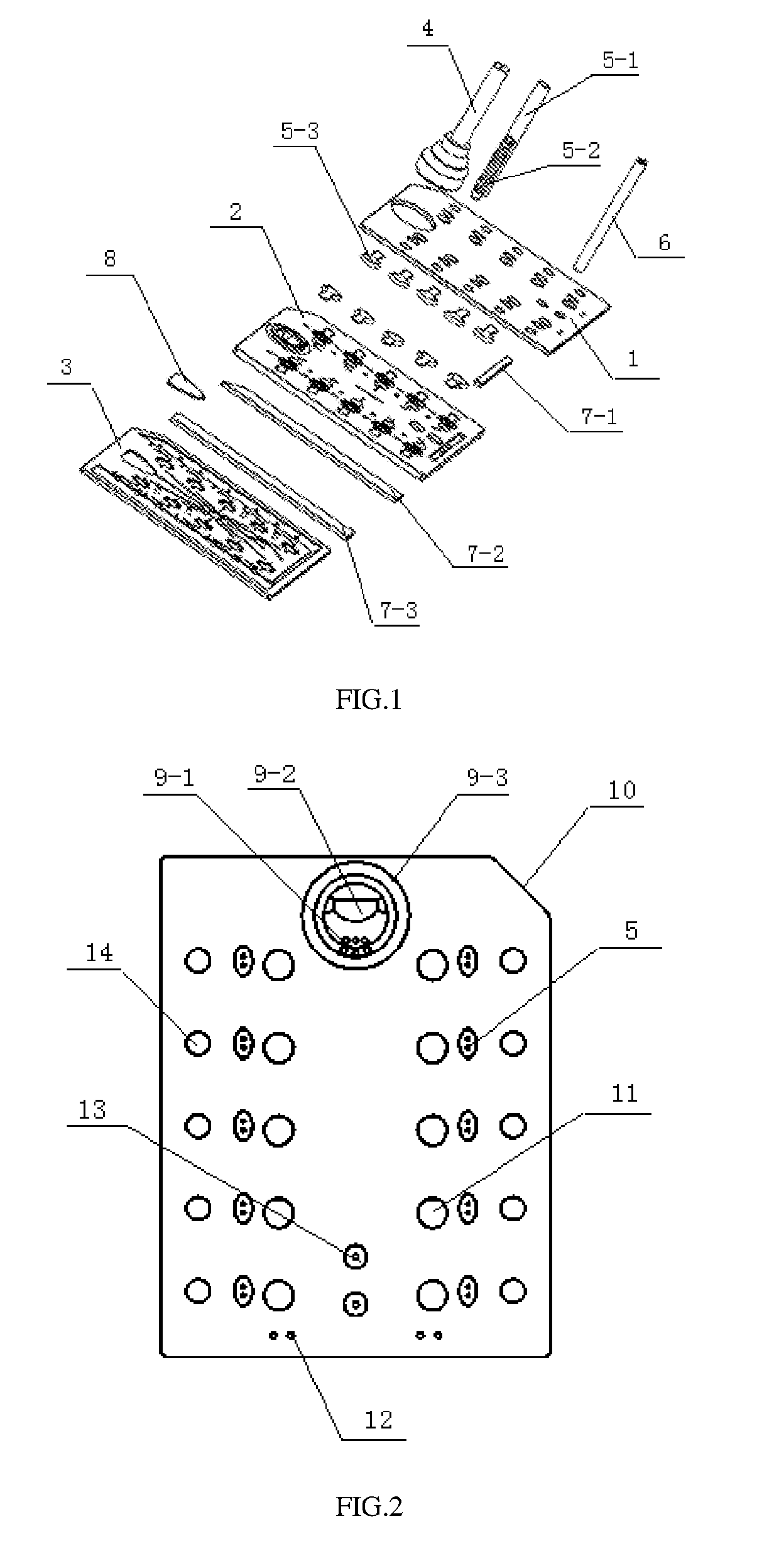
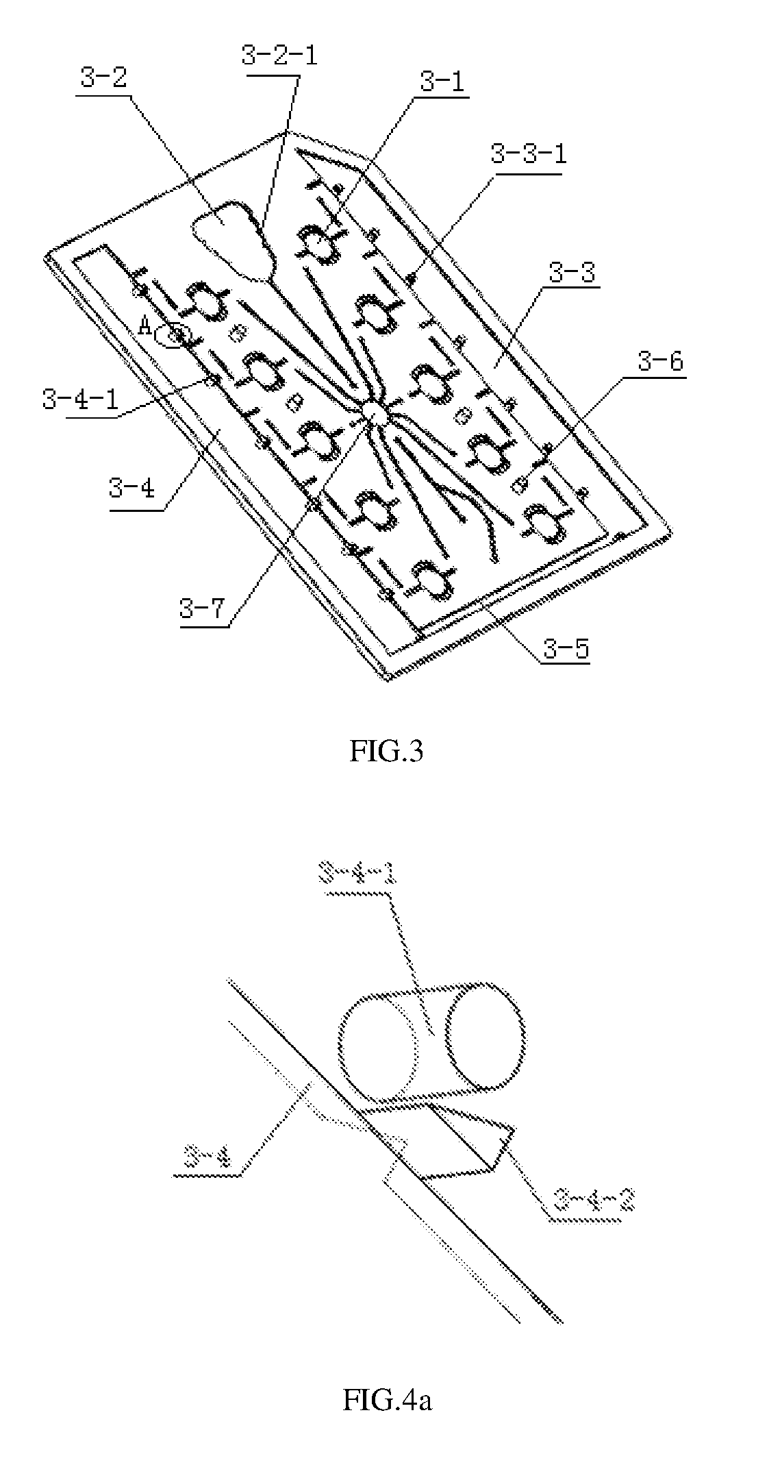
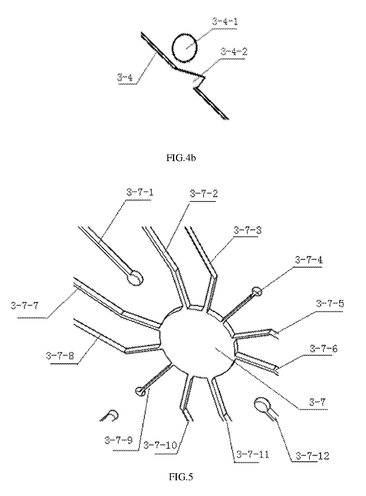
The present invention is a multi-flux micro-fluidic chip based on active fluid flow control that can evenly divide one fluid path into multiple fluid path branches creatively. This allows for the detection of multiple items at the same time, greatly improving the flux of the chip. The design includes valve devices and anti-backflow devices creatively designed by the company that cooperate with the air path for providing forward thrust for fluid control. The chip can be operated by one instrument at the same time, improving the flux and saving time. Overall, the present invention solves defects of the prior art and achieves true micro-fluidic.

Problems solved by technology

In an immunochromatographic reaction system, the coefficient of variation (CV) is large due to system factors, and consequentially, precise quantification cannot be achieved.
However, due to different viscosities of different samples and particularly whole blood samples, uniform fluid velocities are unavailable.

Method used


Image

  • Multi-flux micro-fluidic chip based on active fluid flow control
  • Multi-flux micro-fluidic chip based on active fluid flow control
  • Multi-flux micro-fluidic chip based on active fluid flow control

Examples


Embodiment Construction

[0078]A clear and complete description of the technical scheme of the embodiments of the present invention is given as follows in combination with the drawings in the embodiments. Obviously, the embodiments in the following description are only part of embodiments of the present invention instead of being all embodiments of the present invention. The following description of at least one embodiment by a typical example is actually illustrative solely and is by no means restrictive to the present invention and application or use of the present invention. All other embodiments obtained based on the embodiments of the present invention by those ordinarily skilled in this field without creative work should fall within the protection scope of the present invention. Without additional specifications, relative configurations of components and steps, expressions and numerical values mentioned in these embodiments do not limit the scope of the present invention. Meanwhile, it would appreciat...


PUM


Abstract

Provided is a multi-flux micro-fluidic chip including a chip body. The chip body includes a fluid inflow cavity communicated with an external air path, reaction-quantification cavities, waste liquid cavities, and a fluid path distribution cavity disposed at a middle position of the chip body. The two or more reaction-quantification cavities are distributed on two sides of the fluid path distribution cavity in rows to form the first and second row of reaction-quantification cavities respectively; and they are communicated with a fluid outlet of the fluid path distribution cavity through fluid path branches, and a fluid inlet of the fluid path distribution cavity through fluid path branches, and a fluid inlet of the fluid path distribution cavity is communicated with a fluid outlet of the fluid inflow cavity and an external fluid path, which making it possible to detect multiple items simultaneously and greatly improving the flux of the micro-fluidic chip.

Description

BACKGROUND OF THE INVENTIONTechnical Field[0001]The present invention relates to a micro-fluidic chip based on active fluid flow control, in particular to a multi-flux micro-fluidic chip.Description of Related Art[0002]As a stable and practical technique, lateral flow immunoassay is suitable for point-of-care testing (POCT) of various types or field service.[0003]In an immunochromatographic reaction system, the coefficient of variation (CV) is large due to system factors, and consequentially, precise quantification cannot be achieved. Immunodiagnosis methods based on the micro-fluidic technology can effectively solve these problems.[0004]Micro-fluidic includes passive micro-fluidic and active micro-fluidic, wherein passive micro-fluidic still relies on capillary force to achieve forward lateral chromatography of fluid. However, due to different viscosities of different samples and particularly whole blood samples, uniform fluid velocities are unavailable.[0005]Active micro-fluidic c...

Claims


Application Information

Patent Timeline
IPC IPC(8): G01N33/558G01N33/543F16K99/00B01L3/00
CPCG01N33/558G01N33/54393F16K99/0042B01L3/502746B01L2200/10B01L2400/082B01L3/5027B01L2300/0887B01L2300/0861B01L3/50273B01L3/502738B01L2300/069B01L2300/0864B01L2300/0874B01L2400/0487B01L2400/0655B01L2400/084B01L2300/0867
Inventor XU, XINGSHANGCHEN, JEFFERYWANG, LONGSUN, WEIYANWAN, QILUYANG, SHEN
Owner NANJING LANSION BIOTECH CO LTD
Learn More