
Method for improving flux in a membrane bioreactor

Active Publication Date: 2006-12-07
ECOLAB USA INC
View PDF23 Cites 28 Cited by
  • Summary
  • Abstract
  • Description
  • Claims
  • Application Information

AI Technical Summary

Benefits of technology

[0018] The present invention also provides for a method of improving flux in a membrane bioreactor which comprises one or more anaerobic digesters. An effective amount of one or more cationic, amphoteric, or zwitterionic polymers or combination thereof is added to this type of membrane bioreactor.

Problems solved by technology

In the aerobic membrane bioreactor (MBR) process, membrane fouling has always been a significant issue limiting the hydraulic performance of the process.
Due to membrane fouling, MBR throughput or flux often decreases and more membranes are required to compensate for the throughput loss.
The same microbiologically produced polysaccharide and protein biopolymers produced in MBRs that cause membrane fouling are also known to cause foaming in the MBR mixed liquor.
Therefore, if the MBR contains anoxic and anaerobic reactors, the previous method (John et al, 2004) will be considerably less effective in terms of dosage and flux improvement.
In addition, the previous method would not be effective in anaerobic MBRs, which includes anaerobic digester as a sole bioreactor or one of the bioreactors.
Aeration in the treatment tank (and in the membrane tank) can lead to inorganic fouling by various routes.

Method used


Image

  • Method for improving flux in a membrane bioreactor
  • Method for improving flux in a membrane bioreactor
  • Method for improving flux in a membrane bioreactor

Examples


example 1

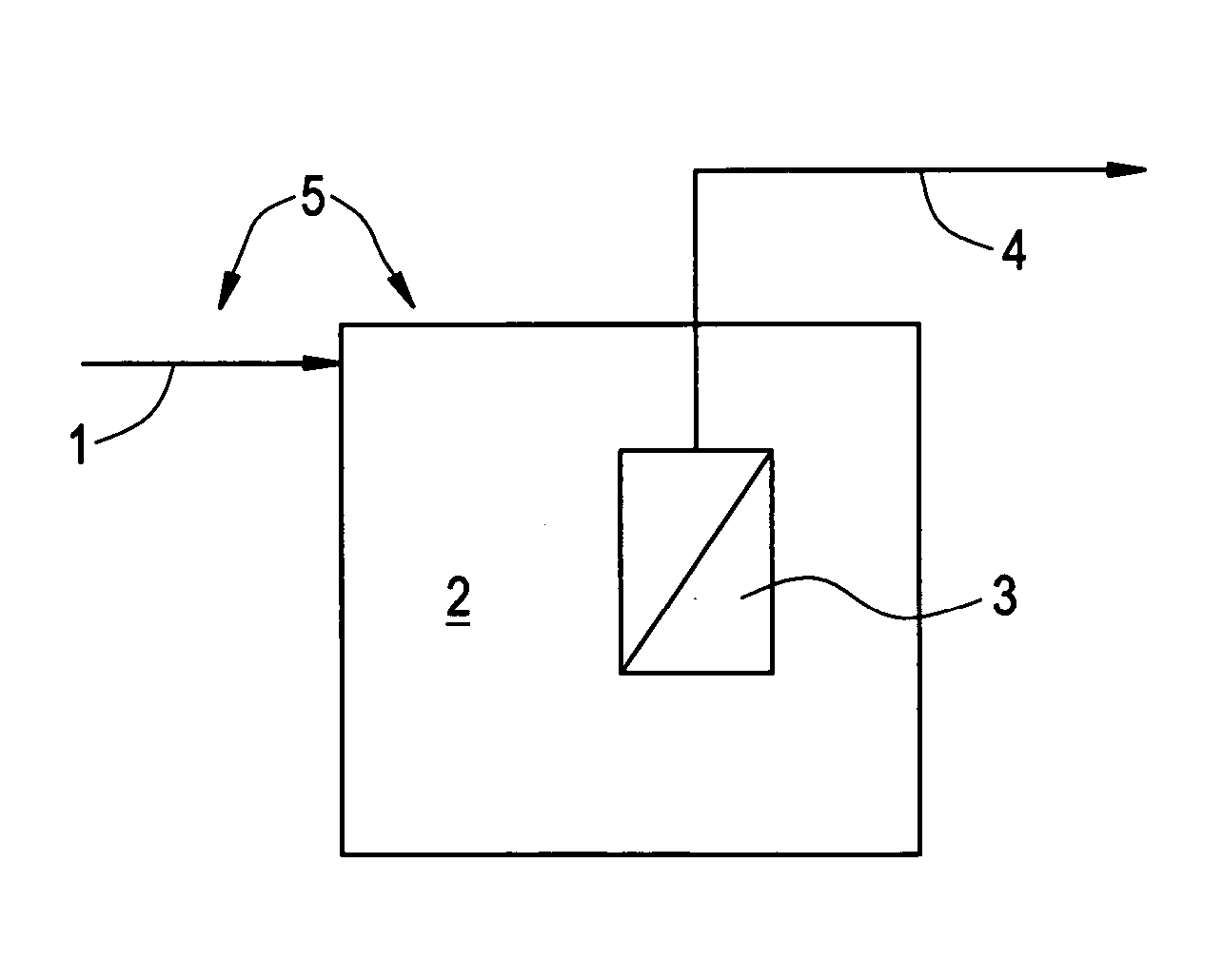
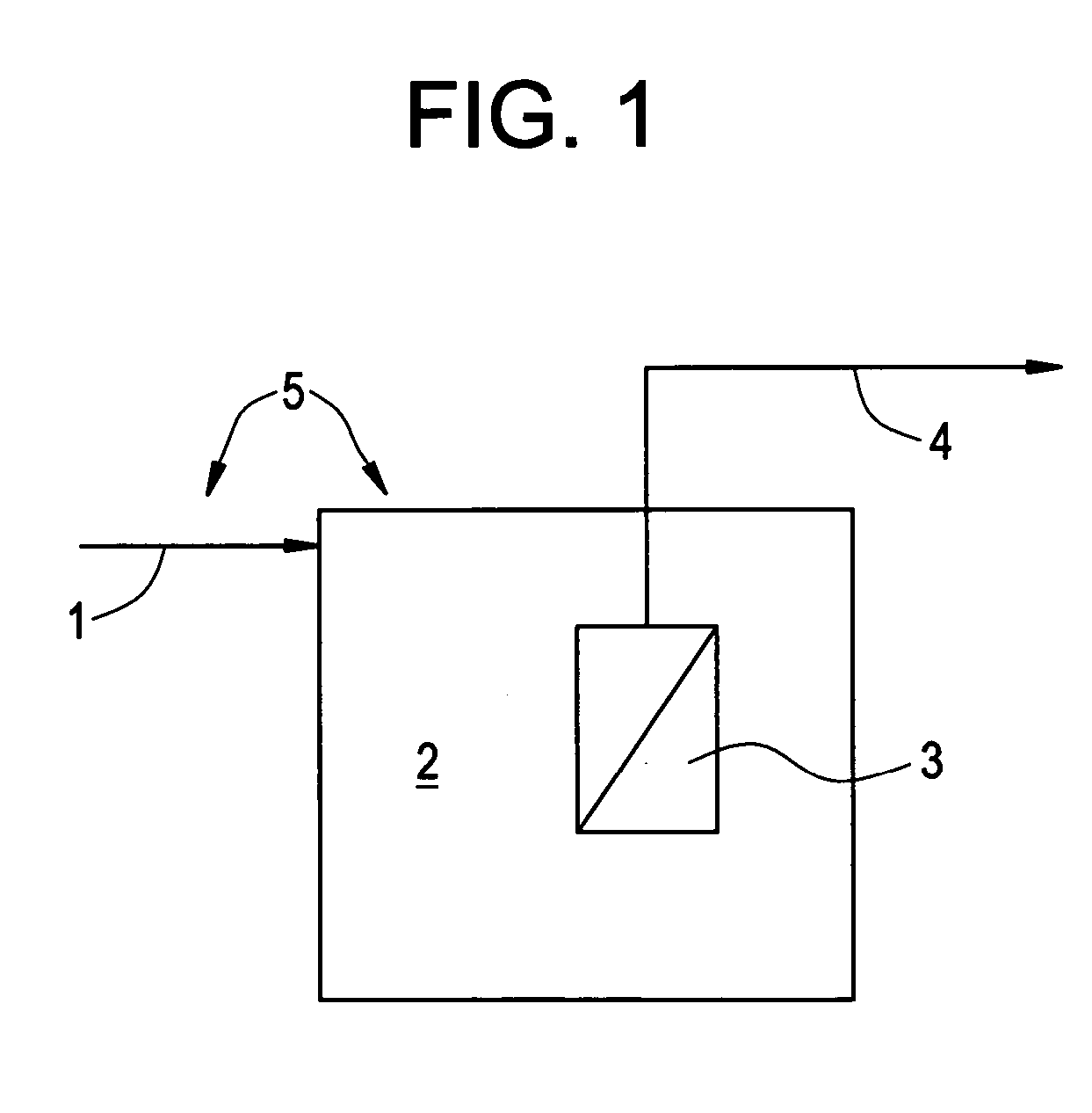
[0050] In FIG. 2, membranes (3) are directly submerged in the aeration tank (2). The aeration tank can be divided by multiple numbers of reactors. Membranes can be submerged to one of the reactors or can be installed outside of the reactor. The MLSS of the mixed liquor can be maintained between 3,000 mg / L and 30,000 mg / L. When influent (1) has higher than 5 ppm of calcium ion and / or higher than 5 ppm of magnesium and / or higher than 10 ppm of silica and / or higher than 0.1 ppm iron, scale formation or inorganic fouling can occur on the membrane surface. Cationic polymers having a MW of 10,000-20,000,000 Da and charge of 1-100% can be added directly to the one of the tanks (5) or any of the streams flowing to one of the reactors at a concentration of 10-2,000 ppm as active polymer. The upper limit of MW is limited only by the solubility or dispersibility of the polymer in water.

example 2

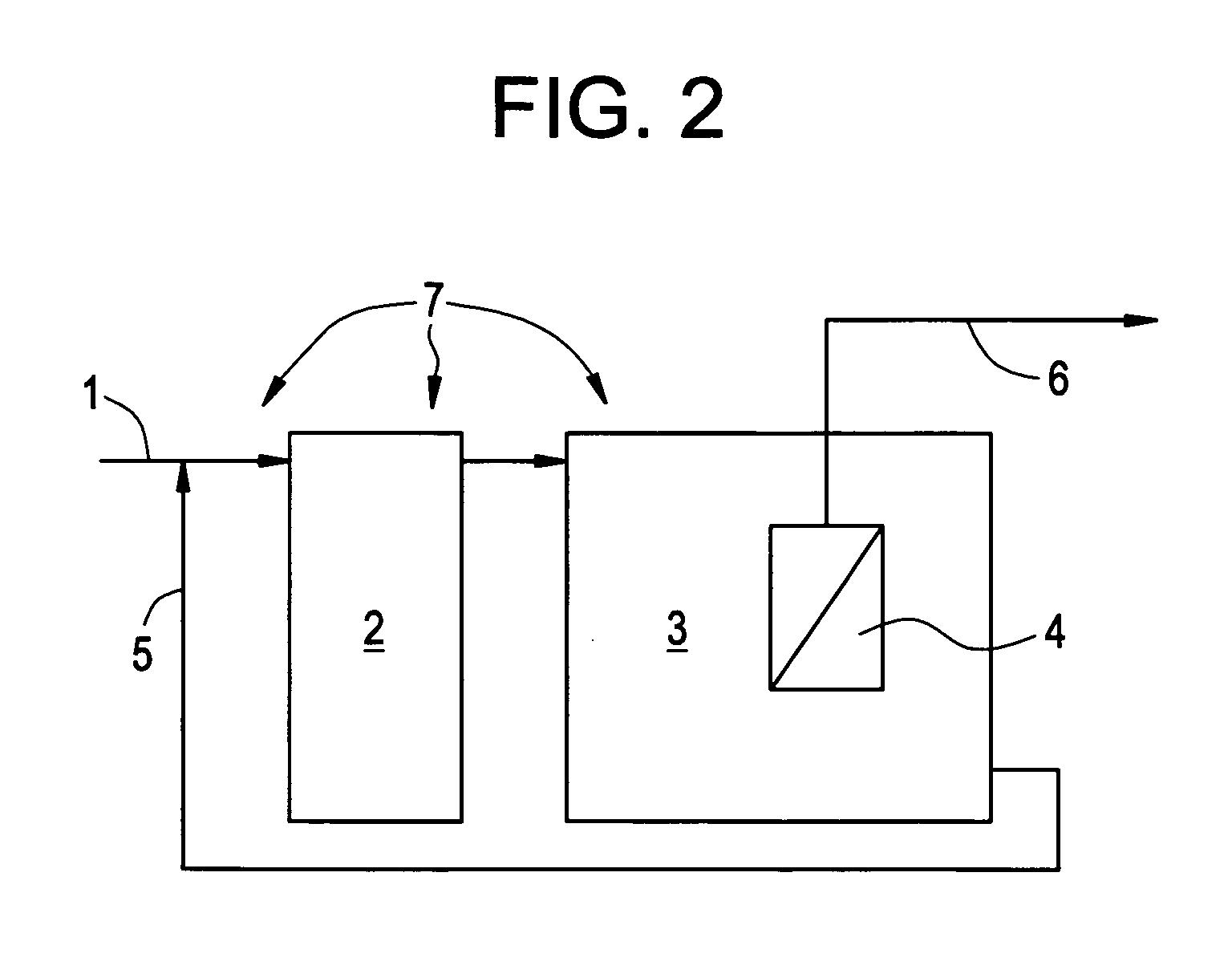
[0051] In FIG. 2 anoxic tank (2) is added to the aeration tank (3) and mixed liquor in the aeration tank is recycled to the anoxic tank, where no air is supplied to maintain dissolved oxygen level at 3) and recycled to anoxic tank (2). In the anoxic tank, some denitrifying bacteria utilize the combined oxygen contained in the nitrate ions and produce nitrogen gas. The membrane configuration can be flat sheet, hollow fiber, tubular, or combinations of these. Optionally membranes can be placed outside of membrane tank and the sludge in one of the tanks can be circulated to the membrane system by pump(s). When influent (1) has higher than 5 ppm of calcium ion and / or higher than 5 ppm of magnesium and / or higher than 0.1 ppm of iron and / or higher than 10 ppm of silica, scale formation or inorganic fouling can occur on the membrane surface.

[0052] Though a broad range of cationic polymers are helpful to prevent membrane fouling, high M.W. (>50,000 Da) and high mole charge (>10%) polymers ...

example 3

[0053] In FIG. 3, an anaerobic (2) and an anoxic (3) tank are added to the aeration tank (4) together for maximum phosphorous removal. Though the mixed liquor recycled from the anoxic tank to the anaerobic tank (7) contains some nitrate ions, the overall oxygen supply is extremely limited since DO level is less than 0.1 mg / L. Even in this environment, some phosphorous accumulation organisms (PAOs) can obtain energy by hydrolyzing the polymeric form of phosphorous that was accumulated in the cell. Once PAOs move to aeration tank through the anoxic tank, they overly accumulate phosphorous for the future use, which is the so called “Luxury Uptake”. The overly accumulated phosphorous is eventually removed when excess biosolids are removed from the system. The membrane configuration can be flat sheet, hollow fiber, tubular, or a combination of these. Optionally the membranes can be placed outside of the tanks and the sludge can be circulated through the membranes to the tanks by pumps. W...


PUM


Abstract

The invention pertains to a method(s) of improving flux in a membrane bioreactor by adding an effective amount of catonic, amphoteric, and zwitterionic polymers, or a combination thereof. The membrane bioreactor impacted by the addition of these polymers is made up of a combination of anaerobic reactors, anoxic reactors, and aerobic reactors and anaerobic digesters.

Description

TECHNICAL FIELD [0001] This invention concerns the use of water soluble cationic, amphoteric or zwitterionic polymers, or a combination thereof to increase water flux through membranes in membrane bioreactors. BACKGROUND OF THE INVENTION [0002] The membrane bioreactor (MBR) unit combines two basic processes: biological degradation and membrane separation-into a single process where suspended solids and microorganisms responsible for biodegradation are separated from the treated water by a membrane filtration unit. The entire biomass is confined within the system, providing for both control of the residence time for the microorganisms in the reactor (mixed liquor age) and the disinfection of the effluent. [0003] In general, influent enters the bioreactor, where it is brought into contact with the biomass. [0004] The mixture is filtered through the membrane using a pump, water pressure or a combination of both. The permeate is discharged from the system while the entire biomass is mai...

Claims


Application Information

Patent Timeline
IPC IPC(8): A01M23/34B01D61/16C02F1/00C02F1/44C02F1/56C02F3/12C02F5/12C12M
CPCB01D61/16B01D61/147B01D2311/12B01D2311/16B01D2321/168C02F1/001C02F1/44C02F1/56C02F3/1268C02F3/1273C02F3/2853C02F5/12B01D2311/04B01D61/145Y02W10/10C12N1/02
Inventor YOON, SEONG-HOONCOLLINS, JOHN H.KOPPES, JEROEN A.HUISMAN, INGMAR H.
Owner ECOLAB USA INC
Learn More