
Speckle laser device based on low time coherence and low spatial coherence, and preparation method therefor

Inactive Publication Date: 2019-05-09
PAVILION INTEGRATION CORP SUZHOU
View PDF7 Cites 0 Cited by
  • Summary
  • Abstract
  • Description
  • Claims
  • Application Information

AI Technical Summary

Benefits of technology

This patent describes a method for creating a speckle-free laser by reducing the time coherence and spatial coherence of the laser output. This is achieved by matching the phase offset of the laser with the coherence length of another laser part or the laser having low coherence properties. By doing so, the laser output has a speckle-free appearance, resulting in a safer and more stable laser output. This technology can be used in various applications such as laser displays or optical communication.

Problems solved by technology

The laser speckle not only causes energy loss, but also becomes a main factor that limits image quality and reduces an image resolution and a contrast.
This method is complex in operation and low in connection stability of the optical path.
However, at present, the dynamic speckle method adopted is complex in structure and is poor in system stability.
The speckle inhibition effect is reduced due to the foregoing factors, and meanwhile, the incident light beam is relatively low in energy utilization rate and large in energy loss after passing through the liquid crystal device and the frosted glass, and the performance of the system is affected due to an angle expansion phenomenon.
In the process, the two methods merely reduce the impacts of the laser speckles on the performance of the system, but cannot evaluate the system in real time and reduce or compensate the system, thereby obtaining image data having low speckle impact and a high signal-to-noise ratio.

Method used


Image

  • Speckle laser device based on low time coherence and low spatial coherence, and preparation method therefor

Examples


Embodiment Construction

[0022]The objectives, advantages, and features of the present invention will be illustrated and explained by way of non-limiting description of the following preferred embodiments, and these embodiments are only typical examples that apply the technical solutions of the present invention. All technical solutions formed by adopting equivalent replacement or equivalent transformation fall within the protection scope of the present invention.

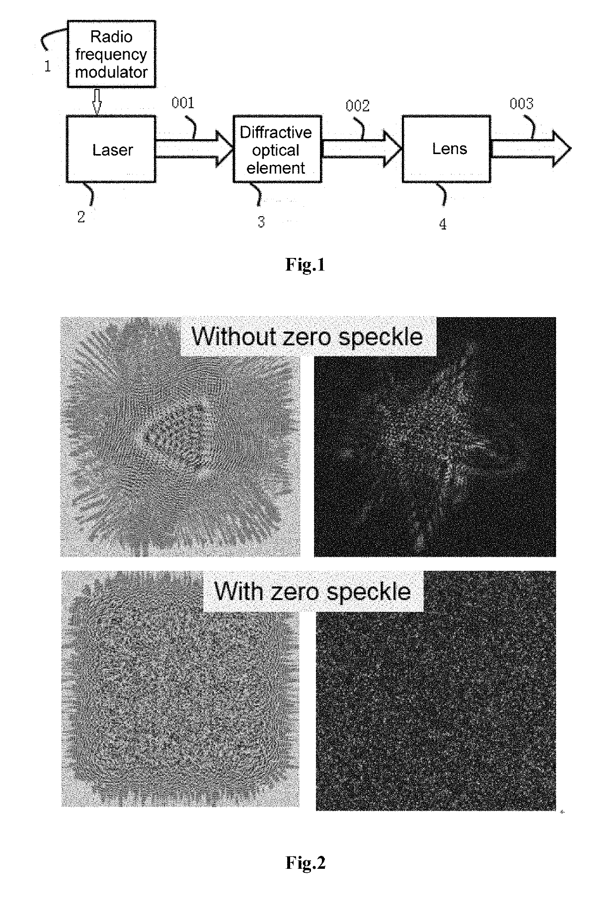
[0023]As shown in FIG. 1, a speckle-free laser based on low time coherence and low spatial coherence is provided, including a radio frequency modulator 1 for reducing time coherence of laser beams, a laser 2, a diffractive optical element 3 for reducing spatial coherence of the laser beams, and a focusing lens 4 that are coaxially and sequentially disposed on a same optical platform.

[0024]In this embodiment, the laser 2 is preferably a semiconductor laser. Selecting the semiconductor laser has the advantages that: the semiconductor laser has a wide...


PUM


Abstract

A speckle laser device based on low time coherence and low spatial coherence, and a preparation method therefor. The speckle laser device comprises a radio frequency modulator (1), a laser device (2), a diffracting optical element (3) and a focusing lens (4) that are coaxially and sequentially disposed on a same optical platform. The diffracting optical element (3) is located in the emergent direction of the laser device (2), the radio frequency modulator (1) modulates the laser device (2), and laser (001) modulated by the radio frequency modulator (1) enters the diffracting optical element (3). Laser beams emerging from the diffracting optical element (3) are zero-coherent speckle laser beams (002), the laser beams (002) enter the focusing lens (4), and the laser emerging from the focusing lens (4) forms a focused speckle laser (003). Speckle laser output beams are obtained by using a time coherence and spatial coherence reduction technology, and the problem of speckle production due to time coherence and spatial coherence is resolved.

Description

FIELD OF THE PRESENT DISCLOSURE[0001]The present invention relates to the technical field of lasers, and in particular to a speckle-free laser based on low time coherence and low spatial coherence and a manufacturing method therefor.BACKGROUND OF THE PRESENT DISCLOSURE[0002]Laser has the characteristics of high brightness, high coherence, high collimation, and the like, and therefore is widely applied in aspects such as industry, communication, medical treatments, laser detection and measurement, and instruments. The laser has a light beam that is highly coherent and has different amplitudes and phases, and irregularly distributed granular speckles-laser speckles are formed at each point in a space. The laser speckle, serving as a random process, is an objective physical phenomenon that necessarily exists due to use of a laser. The laser speckle not only causes energy loss, but also becomes a main factor that limits image quality and reduces an image resolution and a contrast. For e...

Claims


Application Information

Patent Timeline
IPC IPC(8): G02B27/48H01S5/00G02B27/42
CPCG02B27/48H01S5/0085G02B27/4205H01S5/005H01S5/06213H01S5/0622H01S2301/02
Inventor LUO, NINGYIFAN, HUI
Owner PAVILION INTEGRATION CORP SUZHOU
Learn More