Free-Piston Engine

a free-piston engine and free-piston technology, applied in the direction of machines/engines, non-mechanical valves, valve drives, etc., can solve the problems of under-powering performance of advanced fpe designs, unable to expand the technology to other configurations, and difficult to produce useful power levels from advanced designs

Active Publication Date: 2019-05-23
JOHNSON ALAN KENT
View PDF0 Cites 20 Cited by
  • Summary
  • Abstract
  • Description
  • Claims
  • Application Information

AI Technical Summary

Benefits of technology

[0018]A further object of the invention is to provide power piston lubrication without allowing lubricating oil contamination of the combustion chamber. This objective is attained by providing a oil cavity around the circumference of the power piston. The oil cavity is sealed between two piston rings. Flow of lubricating oil enters the cavity via either one or both of two mechanisms. The first mechanism comprises an injector located on the combustion cylinder, operated so that oil is injected into the cavity as the piston passes under the injector. The second mechanism provides oil flow into the cavity through an oil channel in one of the piston's connecting rod. An additional connecting rod provides a channel for oil outflow from the cavity. A pop-top style poppet valve is provided in the power piston to provide for uniflow passage of scavenging air through the piston in a manner that prevents oil seepage into either the combustion chamber or scavenging air supply.

Problems solved by technology

Difficulties have prevented the technology from expanding to other configurations.
Producing useful power levels from advanced designs has proved especially difficult.
One reason for the under-powered performance of advanced FPE designs is that they require reciprocating plungers of significantly heavier weight than conventional FPE's.
Furthermore, the idling cycle rate is the maximum cycle rate of the engine because linkage to a load only dampens and slows the oscillation regardless of fuel burn.
FPE designs having heavy plunger weights thus tend to suffer low engine speeds and low power performance.
If an automotive sized FPE is limited to a cycle rate of only a hundred or so cycles per minute, it is not capable of producing a power level comparable to conventional internal combustion engines.
But such high compression ratios are not practical for an internal combustion engine.
But to attain useful cycle rates at reasonable compression ratios this method yields unworkably large combustion chambers (50).
Control of the engine's stroke length has also proved problematic for advanced FPE's designed to run at standard compression ratios.
That is, small variations in the oscillating system's energy produces large variations in stroke length.
This trait leads to a common problem in advanced FPE's: piston head-strikes.
These methods are complex and costly, and have not been sufficiently developed.
A further disadvantage of current advanced FPE designs is their fixed engine speed.
This approach adds cost and complexity to the engine and reduces efficiency.
Designs that operate valves directly from plunger movement suffer the disadvantage of fixed valve timing that is difficult to adjust.
An additional issue associated with advanced FPE's involves the two-stroke engine cycle.
Other than in large marine engines, the two-stroke engine cycle is commonly implemented in a manner that produces worse exhaust emissions and lower thermal efficiency than four-stroke engines.
Current advanced FPE designs have not sufficiently addressed this issue.
Finally, advanced free-piston designs are usually limited to single cylinder configurations.
Opposed-piston types are limited to two combustion chambers and reciprocating plungers.
Additionally, cumbersome mechanical linkages are needed to synchronize the plungers in opposed-piston FPE's.
The scheme suffers serious vibration issues because the motion of the plungers is unsynchronized.

Method used


Image

  • Free-Piston Engine
  • Free-Piston Engine
  • Free-Piston Engine

Examples


Embodiment Construction

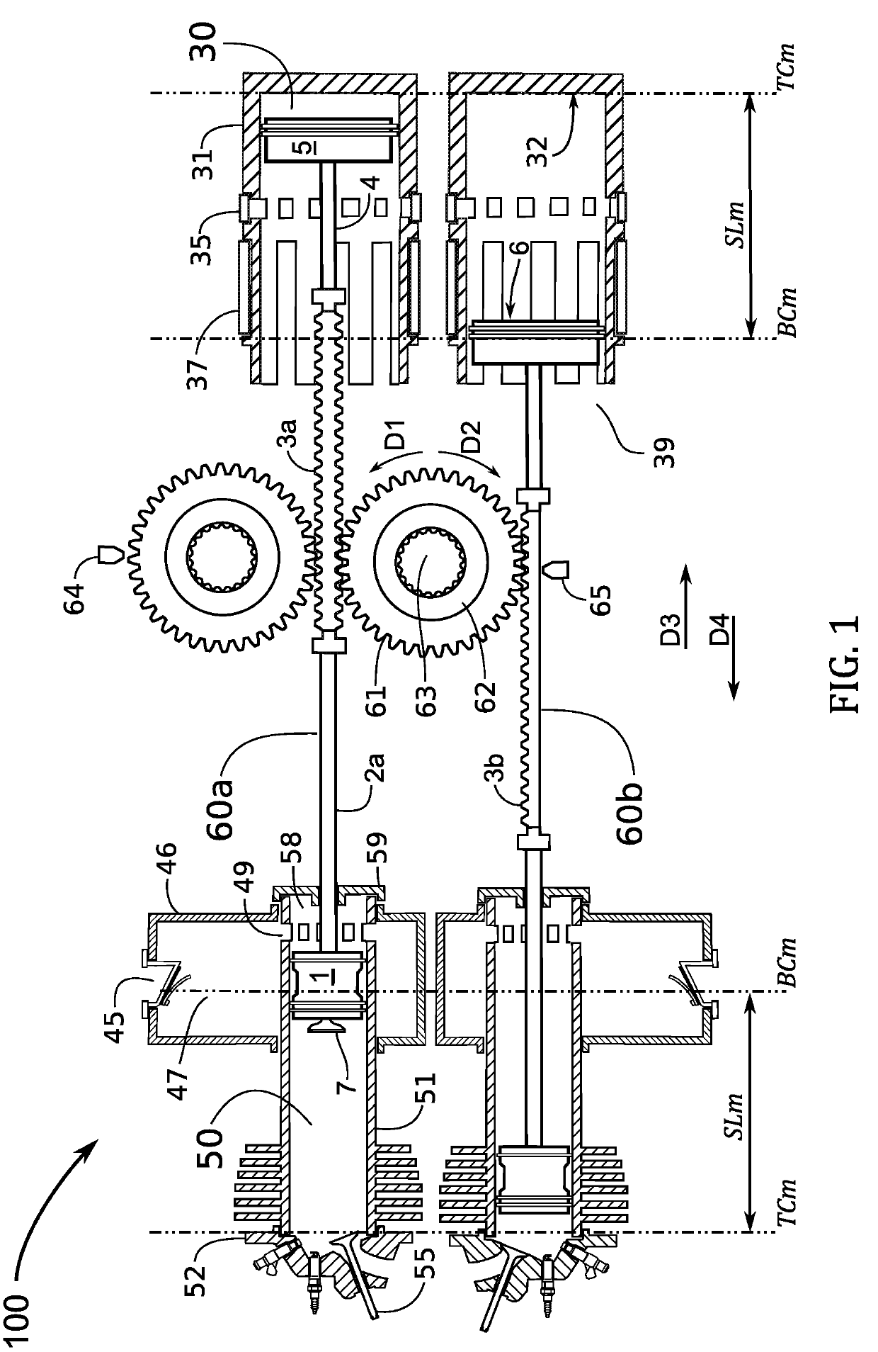
[0066]For the spatial terminology of the disclosure FIG. 1 will be used as the reference orientation. The following terminology is presented for descriptive purposes and is not meant to imply functionality. That is, for example, when the term “upper chamber” is used it does not imply that the engine must be orientated in practice with the identified “upper chamber” facing upwards. The terms “upper” and “lower” will refer to the top and bottom of FIG. 1. When discussing two parts having identical functions the suffix a and b may be attached to signify the upper part and lower part. For example, plunger 60a will designate the upper plunger and plunger 60b will designate the lower plunger. The term “inboard” will refer to directions D3 or D4 when the directions point toward the center of FIG. 1. The term “outboard” will refer to directions D3 or D4 when the directions point toward the left-most or right-most sides of FIG. 1. For example, combustion head 52 seals the outboard side of cy...


PUM


Abstract

A multicylinder internal combustion free-piston engine (FPE) with synchronized reciprocating plungers. The invention provides a solution for the problem of the slow engine speed typical of FPE's with heavy plunger mass. Bounce chambers fitted with sleeve valves control the engine's speed and stroke length. The invention's configuration prevents piston head-strikes and operates at standard compression ratios. Piston “pop-top” intake valves allow uniflow scavenging and connecting rod oil channels provide lubrication with no combustion chamber contamination. Poppet combustion head valves are operated by linear cams attached to the plungers. Hydraulic valve actuators implement variable valve timing under computer control.

Description

TECHNICAL FIELD[0001]The present invention relates generally to the field of internal combustion free-piston engines. More specifically the present invention relates to a multi-cylinder internal combustion free-piston engine capable of operating at a high cycle rate even with a heavy reciprocating mass, and capable of operating at an adjustable cycle rate.BACKGROUND[0002]Internal combustion engines of the free-piston type are known and have been successfully manufactured as air compressors, gas generators for turbine engines, and as hydraulic pumps. These types may be called “conventional” free-piston engines. Difficulties have prevented the technology from expanding to other configurations. A large body of literature exists on the potential of using an internal combustion free-piston engine (FPE) to drive a linear electric generator. Attempts have also been made to convert the reciprocating action of a free-piston engine directly to rotational power by use of rack-and-pinion mechan...

Claims


Application Information

Patent Timeline
Patent Type & Authority Applications(United States)
IPC IPC(8): F02B71/04F01L1/14F01L1/38F01L9/02F02B33/04F01M1/06F01L9/11F01L9/12
CPCF02B71/04F01L1/146F01L1/38F01L9/023F02B33/04F01M1/06F01M2001/066F01B11/009F01B11/08F01L1/04F01L1/181F01L3/205F01L7/045F01L21/00F01B9/047F02B33/06F01L2305/00F01L9/11F01L9/12
Inventor JOHNSON, ALAN KENT
Owner JOHNSON ALAN KENT
Why Eureka
Try Eureka