Gas turbine and method for operating gas turbine

Active Publication Date: 2019-05-23
MITSUBISHI POWER LTD
View PDF0 Cites 7 Cited by
  • Summary
  • Abstract
  • Description
  • Claims
  • Application Information

AI Technical Summary

Benefits of technology

[0038]According to the gas turbine and the method for operating a gas turbine according to the above aspects of the present invention, the control device which opens the exhaust valve and operates the driving fluid supply device, when the operating state of the gas turbine is in the region where the rotating stall occurs, is provided, and therefore, some of the compressed air bled from the compressor is increased in speed by the ejector and exhaus

Problems solved by technology

When compressed air is generated in this compressor, a load on compressor blades increases, and thus a rotating stall (surging) occurs.

Method used


Image

  • Gas turbine and method for operating gas turbine
  • Gas turbine and method for operating gas turbine
  • Gas turbine and method for operating gas turbine

Examples


Example

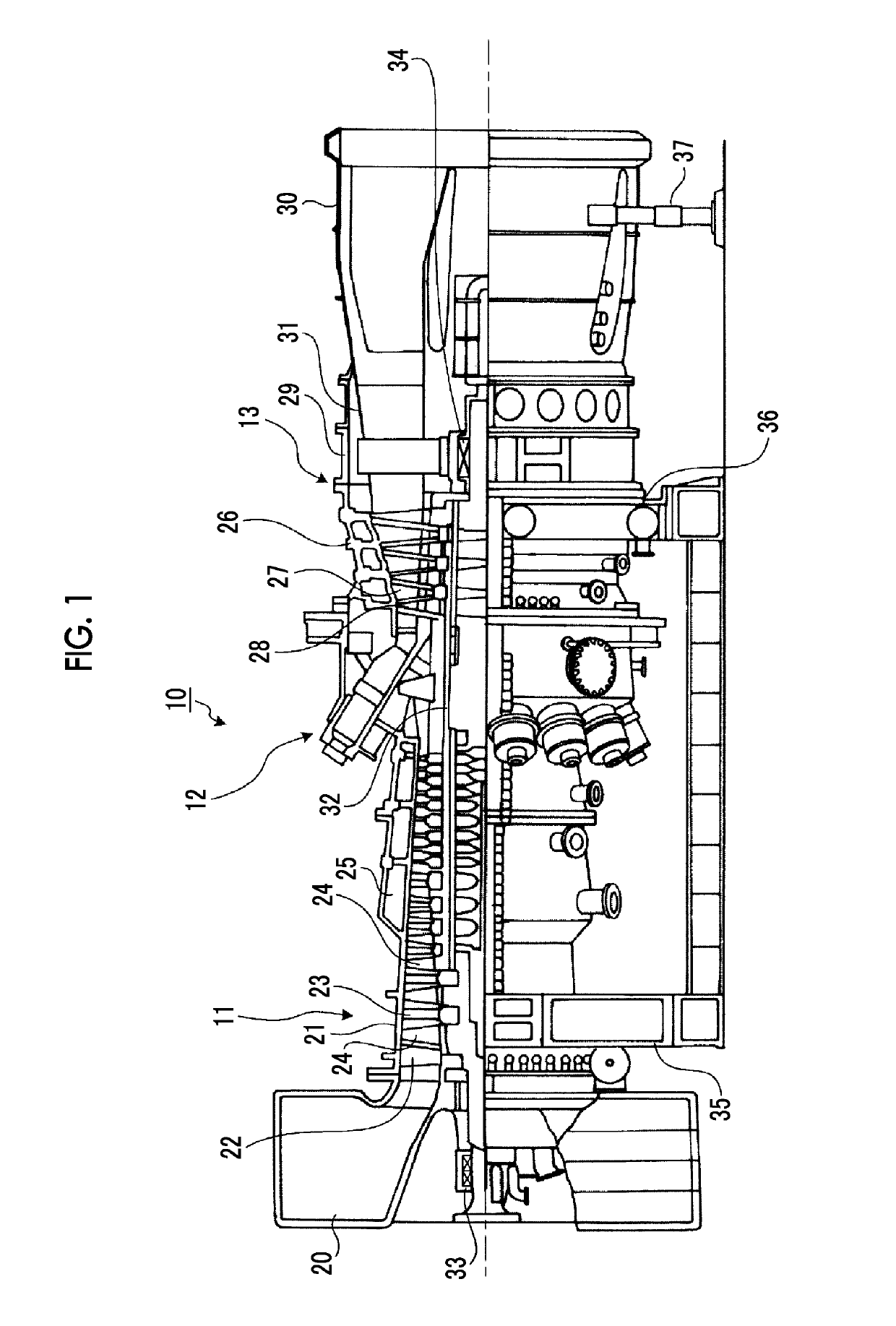
[0049]FIG. 1 is a schematic configuration diagram showing a gas turbine of a first embodiment.

[0050]In the first embodiment, as shown in FIG. 1, a gas turbine 10 includes a compressor 11, a combustor 12, and a turbine 13. A power generator (not shown) is coaxially connected to the gas turbine 10, and thus the gas turbine 10 is made to be able to generate electric power.

[0051]The compressor 11 has an air intake port 20 for taking in air, and in a compressor casing 21, an inlet guide vane (IGV) 22 is disposed and also a plurality of compressor vanes 23 and a plurality of compressor blades 24 are alternately disposed in a front-rear direction (an axial direction of a rotor 32 (described later)), and a bleed chamber 25 is provided outside the compressor casing 21. The combustor 12 is made to supply fuel to compressed air compressed in the compressor 11 and be able to burn the fuel-air mixture by igniting it. In the turbine 13, a plurality of turbine vanes 27 and a plurality of turbine b...

Example

Second Embodiment

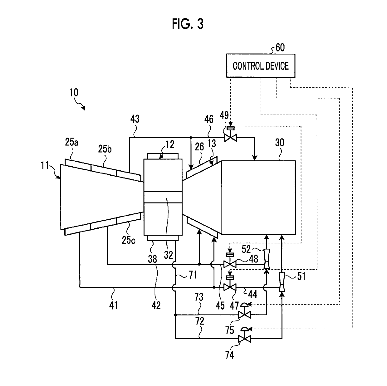
[0084]FIG. 3 is a schematic diagram showing a bleed system of a gas turbine of a second embodiment. Members having the same functions as those in the embodiment described above are denoted by the same reference numerals, and a detailed description thereof is omitted.

[0085]In the second embodiment, as shown in FIG. 3, the gas turbine 10 includes the compressor 11, the combustor 12, and the turbine 13. The configurations and operations of the low-pressure bleed passage 41, the medium-pressure bleed passage 42, the high-pressure bleed passage 43, the low-pressure exhaust passage 44, the medium-pressure exhaust passage 45, the high-pressure exhaust passage 46, the low-pressure exhaust valve 47, the medium-pressure exhaust valve 48, and the high-pressure exhaust valve 49 are the same as those in the first embodiment.

[0086]The low-pressure ejector 51 is disposed further on the downstream side in the flow direction of the compressed air than the low-pressure exhaust valve ...

Example

Third Embodiment

[0094]FIG. 4 is a schematic diagram showing a bleed system of a gas turbine of a third embodiment. Members having the same functions as those in the embodiments described above are denoted by the same reference numerals, and a detailed description thereof is omitted.

[0095]In the third embodiment, as shown in FIG. 4, the gas turbine 10 includes the compressor 11, the combustor 12, and the turbine 13. The configurations and operations of the low-pressure bleed passage 41, the medium-pressure bleed passage 42, the high-pressure bleed passage 43, the low-pressure exhaust passage 44, the medium-pressure exhaust passage 45, the high-pressure exhaust passage 46, the low-pressure exhaust valve 47, the medium-pressure exhaust valve 48, and the high-pressure exhaust valve 49 are the same as those in the first embodiment.

[0096]The low-pressure ejector 51 is disposed further on the downstream side in the flow direction of the compressed air than the low-pressure exhaust valve 47...


PUM


Abstract

A gas turbine equipped with: a low-pressure bleed passage, a medium-pressure bleed passage, and a high-pressure bleed-passage for supplying compressed air bled from respective bleed chambers to a turbine; a low-pressure exhaust passage, a medium-pressure exhaust passage, and a high-pressure exhaust passage for exhausting the compressed air in the respective bleed passages to an exhaust chamber; a low-pressure exhaust valve, a medium-pressure exhaust valve, and a high-pressure exhaust valve provided respectively in the exhaust passages; a low-pressure ejector and a medium-pressure ejector provided in the respective exhaust passages; a driving air supply passage for supplying the compressed air to the ejectors; and a control device that opens the exhaust valves and supplies compressed air from the driving air supply passage to the ejectors when the operating state of a gas turbine is in a region in which rotation stall is generated.

Description

TECHNICAL FIELD[0001]The present invention relates to a gas turbine having a compressor, a combustor, and a turbine, and a method for operating the gas turbine.Background Art[0002]A general gas turbine includes a compressor, a combustor, and a turbine. Then, air taken in through an air intake port is compressed by the compressor, thereby becoming high-temperature and high-pressure compressed air, and in the combustor, fuel is supplied to the compressed air and burns, whereby a high-temperature and high-pressure combustion gas (a working fluid) is obtained, and the turbine is driven by the combustion gas to drive a power generator connected to the turbine.[0003]When the gas turbine is started, compressed air is secured by driving the compressor by drivingly rotating a rotor by a starting motor. When compressed air is generated in this compressor, a load on compressor blades increases, and thus a rotating stall (surging) occurs. If the rotating stall occurs, there is a case where a de...

Claims


Application Information

Patent Timeline
IPC IPC(8): F02C9/28F02C6/08F02C7/26F02C9/18F04D27/02
CPCF02C9/28F02C6/08F02C7/26F02C9/18F04D27/0284F04D27/0215F04D27/023F05D2260/601F05D2260/85F05D2270/101F04D27/02
Inventor KITAGUCHI, YOSHINORI
Owner MITSUBISHI POWER LTD
Why Eureka
Try Eureka