Magnetic resonance imaging apparatus and method

a magnetic resonance and imaging apparatus technology, applied in the field of magnetic resonance imaging, can solve the problems of limiting the acceptance of magnetic resonance in clinical routine, increasing the risk of motion artifacts, and limiting patient throughput, and achieve the effect of fast mr scanning times

Active Publication Date: 2019-05-23
SIEMENS HEALTHCARE GMBH
View PDF3 Cites 10 Cited by
  • Summary
  • Abstract
  • Description
  • Claims
  • Application Information

AI Technical Summary

Benefits of technology

[0011]Accordingly, there is a need for improved MR imaging methods, which overcome the above-mentioned disadvantages. It is, therefore, an objective of the present application to provide such an improved MR imaging method, which is more efficient and allows faster MR scanning times compared to conventional MR imaging methods.

Problems solved by technology

However, SPACE has a number of disadvantages that limit its acceptance in clinical routine.
Such a long scanning time is limiting patient throughput and increases the risk of motion artifacts.
Furthermore, breathhold applications such as for SPACE for MRCP are strongly affected.
However, despite flip angle optimization, the magnetization cannot be kept fully constant over time, which leads to blurring effects along the phase and partition directions.
The combination of Partial Fourier and Wave-CAIPIRINHA is, however, not feasible according to conventional MR imaging methods.
However, the degree of sparsity for static SPACE images is much lower than for dynamic applications.

Method used


Image

  • Magnetic resonance imaging apparatus and method
  • Magnetic resonance imaging apparatus and method
  • Magnetic resonance imaging apparatus and method

Examples


first embodiment

[0068]The following further characteristics of the MR measurement method according to the invention are advantageous for improved MR image quality and reduced MR measurement time. For example, the MR measurement method can be a 3D Turbo Spin Echo (TSE) technique. The RF pulses can be non-selective refocusing pulses. The RF pulses can include excitation, refocusing, and store / recall pulses. The RF pulses can induce variable flip angles. By the above specific configurations of the RF pulses, the length of the echo trains can be increased encompassing more phase encoding steps, which leads to shorter MR measurement or acquisition times. The sequence of k-space measurement points for detecting the undersampled MR measurement data can be ordered corresponding to variable flip angles induced by the RF pulses. In a further embodiment, the method can be adjusted for an isotropic measurement resolution.

second embodiment

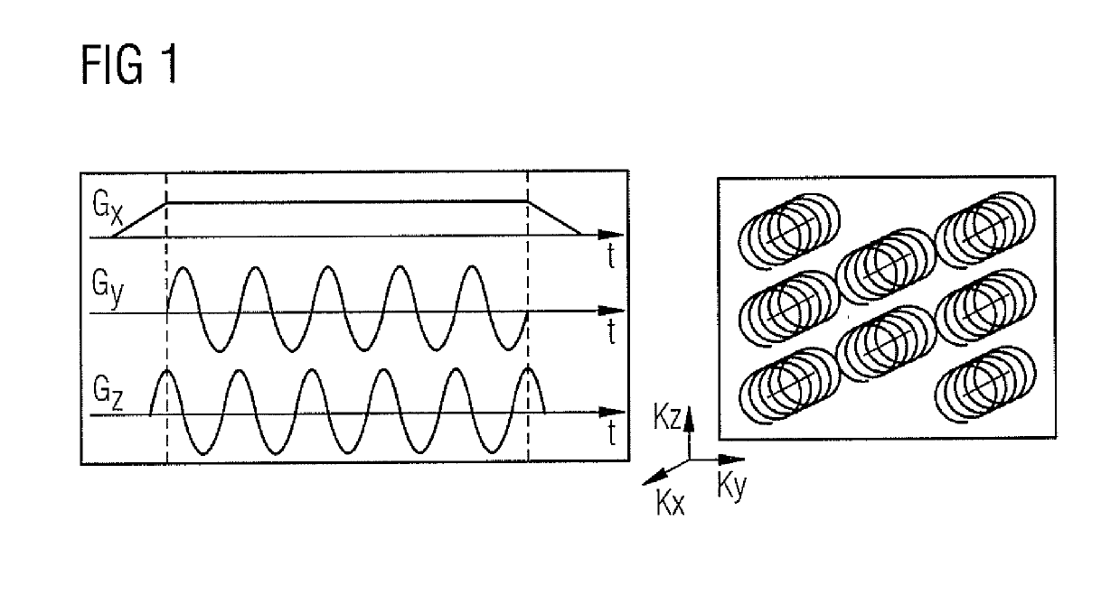
[0069]The MR measurement data according to the invention can be provided using a wave-CAIPI MR measurement method.

[0070]Summarizing, MR imaging methods for generating an MR image of an examination object in a MR apparatus comprising at least two receiving coils are provided, wherein gradient magnetic fields are applied to the examination region concurrent with stimulated echo signals, such that trajectories, which are not constant lines, are generated in k-space. According to a first embodiment of the invention, a sequence of RF pulses is applied to generate stimulated echo signals in the examination object, undersampled MR measurement data are detected during receiving of said stimulated echo signals in the at least two receiving coils using the curved k-space trajectories, and fully sampled MR measurement data are generated from the undersampled MR measurement data using sensitivity information of the at least two receiving coils. According to a second embodiment of the invention,...


PUM


Abstract

Magnetic resonance (MR) data are acquired by applying magnetic fields to an examination region concurrent with stimulated echo signals, such that trajectories, which are not straight lines, are generated in k-space. For this purpose, sequence of RF pulses is applied to generate the stimulated echo signals in the examination object, undersampled MR measurement data are detected during reception of the stimulated echo signals in the at least two receiving coils, along the curved k-space trajectories, and fully sampled MR measurement are generated from the undersampled MR measurement data using sensitivity information of the at least two receiving coils. Alternatively, the MR measurement data are fully sampled in a central region of k-space, and a region outside the central region is not fully sampled, and a phase correction with a Partial Fourier technique is executed on the MR measurement data using fully sampled MR measurement data from the central region of k-space.

Description

BACKGROUND OF THE INVENTIONField of the Invention[0001]The present invention relates to magnetic resonance (MR) imaging and in particular to a MR imaging method using k-space trajectories, which are not constant lines. The invention also encompasses a corresponding MR apparatus and an electronically readable data carrier that implement such a method.Description of the Prior Art[0002]The MR measurement sequence SPACE combines TSE-type contrast (Turbo Spin Echo Sequence, in short TSE) with a possibility for isotropic measurement resolution, i.e. uniform voxels in all directions, paired with a high signal to noise ratio (SNR) by volumetric excitation. However, SPACE has a number of disadvantages that limit its acceptance in clinical routine. In particular, high measurement times are required due to a large number of phase and partition encoding steps required for high spatial resolution in 3 dimensions, such as 1 mm isotropic resolution. For example, a conventional SPACE FLAIR protocol...

Claims


Application Information

Patent Timeline
Patent Type & Authority Applications(United States)
IPC IPC(8): G01R33/561G01R33/48G01R33/56G01R33/58G01R33/565
CPCG01R33/5617G01R33/4822G01R33/5608G01R33/583G01R33/56545G01R33/4818G01R33/5611G01R33/56509
Inventor POLAK, DANIELCHUAH, YEN MEI LISARAITHEL, ESTHER
Owner SIEMENS HEALTHCARE GMBH
Why Eureka
Try Eureka