Rf-powered micromechanical clock generator

a micromechanical clock and generator technology, applied in the direction of electric pulse generator details, pulse manipulation, pulse technique, etc., can solve the problems of high accuracy clock signals that are not readily available at low power, subject to thermal drift, vibration, and energy. likely to pose a major constrain

Active Publication Date: 2019-05-23
RGT UNIV OF CALIFORNIA
View PDF0 Cites 2 Cited by
  • Summary
  • Abstract
  • Description
  • Claims
  • Application Information

AI Technical Summary

Benefits of technology

[0006]Traditional real time clock circuits consume about 1 μW of electrical power, or more, and further are only as accurate as the resonanc

Problems solved by technology

Therefore, high accuracy clock signals are not readily available at low power, and are subject to thermal drif

Method used


Image

  • Rf-powered micromechanical clock generator
  • Rf-powered micromechanical clock generator
  • Rf-powered micromechanical clock generator

Examples


Embodiment Construction

1. Introduction

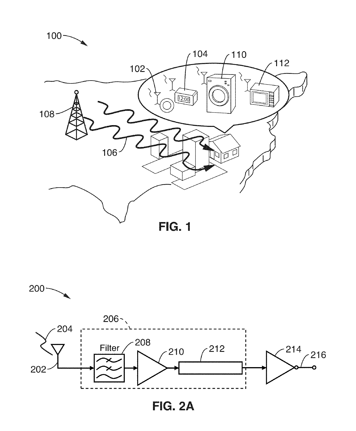
[0068]The widespread expectation that autonomous sensor networks will fuel massively accessible information technology, such as the Internet of Things (IoT), comes with the realization that huge numbers of sensor nodes will be required, perhaps approaching one trillion. Needless to say, besides cost, energy will likely pose a major constraint in such a vision. If sleep / wake strategies can adequately limit a given node's sensor and wireless power consumption, the power bottleneck then concentrates on the real-time clock (RTC) that synchronizes sleep / wake cycles.

[0069]With typical RTC battery consumption on the order of 1 μW, a low-cost printed battery with perhaps 1 J of energy would last only 11.5 days. On the other hand, if a clock could bleed only 10 nW from this battery, it would last 3 years.

[0070]Pursuant to attaining such a clock, this technology explores a wireless approach that eliminates conventional closed-loop positive feedback design to realizing an RTC (a...


PUM


Abstract

A microelectromechanical resonant switch (“resoswitch”) converts received radio frequency (RF) energy into a clock output. The resoswitch first accepts incoming amplitude- or frequency-shift keyed clock-modulated RF energy at a carrier frequency, filters it, provides power gain via resonant impact switching, and finally envelop detects impact impulses to demodulate and recover the carrier clock waveform. The resulting output derives from the clock signal that originally modulated the RF carrier, resulting in a local clock that shares its originator's accuracy. A bare push-pull 1-kHz RF-powered mechanical clock generator driving an on-chip inverter gate capacitance of 5 fF can potentially operate with only 5 pW of battery power, 200,000 times lower than a typical real-time clock. Using an off-chip inverter with 17.5 pF of effective capacitance, a 1-kHz push-pull resonator would consume 17.5 nW.

Description

CROSS-REFERENCE TO RELATED APPLICATIONS[0001]This application claims priority to, and is a 35 U.S.C. § 111(a) continuation of, PCT international application number PCT / US2017 / 029769 filed on Apr. 27, 2017, incorporated herein by reference in its entirety, which claims priority to, and the benefit of, U.S. provisional patent application Ser. No. 62 / 328,114 filed on Apr. 27, 2016, incorporated herein by reference in its entirety, and which claims priority to, and the benefit of, U.S. provisional patent application Ser. No. 62 / 333,182 filed on May 7, 2016, incorporated herein by reference in its entirety. Priority is claimed to each of the foregoing applications.[0002]The above-referenced PCT international application was published as PCT International Publication No. WO 2017 / 189806 A1 on Nov. 2, 2017, which publication is incorporated herein by reference in its entirety.STATEMENT REGARDING FEDERALLY SPONSORED RESEARCH OR DEVELOPMENT[0003]This invention was made with government support...

Claims


Application Information

Patent Timeline
IPC IPC(8): H01H1/00H04L27/152H03K5/135
CPCH01H1/0036H04L27/152H03K5/135H03K3/01H03H9/462H03H9/2426H03H9/505H01H2001/0078
Inventor NGUYEN, CLARK T.-C.LIU, RUONANNAGHSH NILCHI, JALAL
Owner RGT UNIV OF CALIFORNIA
Why Eureka
Try Eureka