Heat Exchanger

a heat exchanger and heat exchange surface technology, applied in indirect heat exchangers, lighting and heating apparatus, transportation and packaging, etc., can solve the problems of requiring a relatively large amount of space, unable to obtain homogenous mixtures with such heat exchangers and static mixers, and achieving high thermal conductivity, high resistance to chemicals, and high quality.

Active Publication Date: 2019-05-30
PROMIX SOLUTIONS
View PDF0 Cites 6 Cited by
  • Summary
  • Abstract
  • Description
  • Claims
  • Application Information

AI Technical Summary

Benefits of technology

[0055]The use of an intermediate jacket element has several advantages. Thus, the insert element can be made much thinner and lighter. Therefore, for the insert element, a different material, for example, a higher quality material, can be used as for the intermediate jacket element. In particular, the insert element may contain a material which has a high thermal conductivity or a high resistance to chemicals, for example a high corrosion resistance. The insert element may be integrally formed with the web elements by an additive manufacturing method or casting method. Since the production of the insert element is very expensive, it can be placed as a semi-finished product in stock and the intermediate jacket element can be adjusted to the required wall thickness depending on the application and nominal pressure. The jacket element, which surrounds the intermediate jacket element, can be designed as a further double jacket, through which the heat transfer fluid flows in the operating state. The heat transfer fluid passes through the openings in the jacket element and in the intermediate jacket element and in the insert jacket element to at least one of the web elements, so that it can flow through the web element or elements.

Problems solved by technology

There is also a small deflection at these ribs or transverse displacement of the fluid flow, which is also limited locally to the environment of the ribs.
Since the ribs are not flowed through by a heat transfer fluid, they offer only a limited effective heat exchange surface and require a relatively large amount of space.
The transverse mixing taking place only over part of the cross section can also lead to the formation of locally different heat profiles and concentration profiles, which may have the consequence that no homogenous mixture can be obtained with such a heat exchanger and static mixer.
It has been found that the production of heat exchangers with thick-walled tubes is very complicated and expensive and, depending on the manufacturing process, qualitative problems can also occur.
The production by casting or by an additive manufacturing process incur high costs, which usually increase linearly with the weight.
The one-piece casting of thick-walled tubes with a complex interior of webs is technically very demanding and often leads to quality problems.
If the usually very complex web structure is to be connected in the interior space, for example by soldering or welding with the outer tube, it is very expensive in a thick-walled outer tube due to the weight and the resulting difficult handling.
Since the wall thickness of such heat exchangers depend on the pressure and temperature of the application and can vary accordingly, they must be manufactured individually according to specification which significantly increases the cost of production and greatly increases the delivery times since prefabrication is not possible.

Method used


Image

  • Heat Exchanger
  • Heat Exchanger
  • Heat Exchanger

Examples


first embodiment

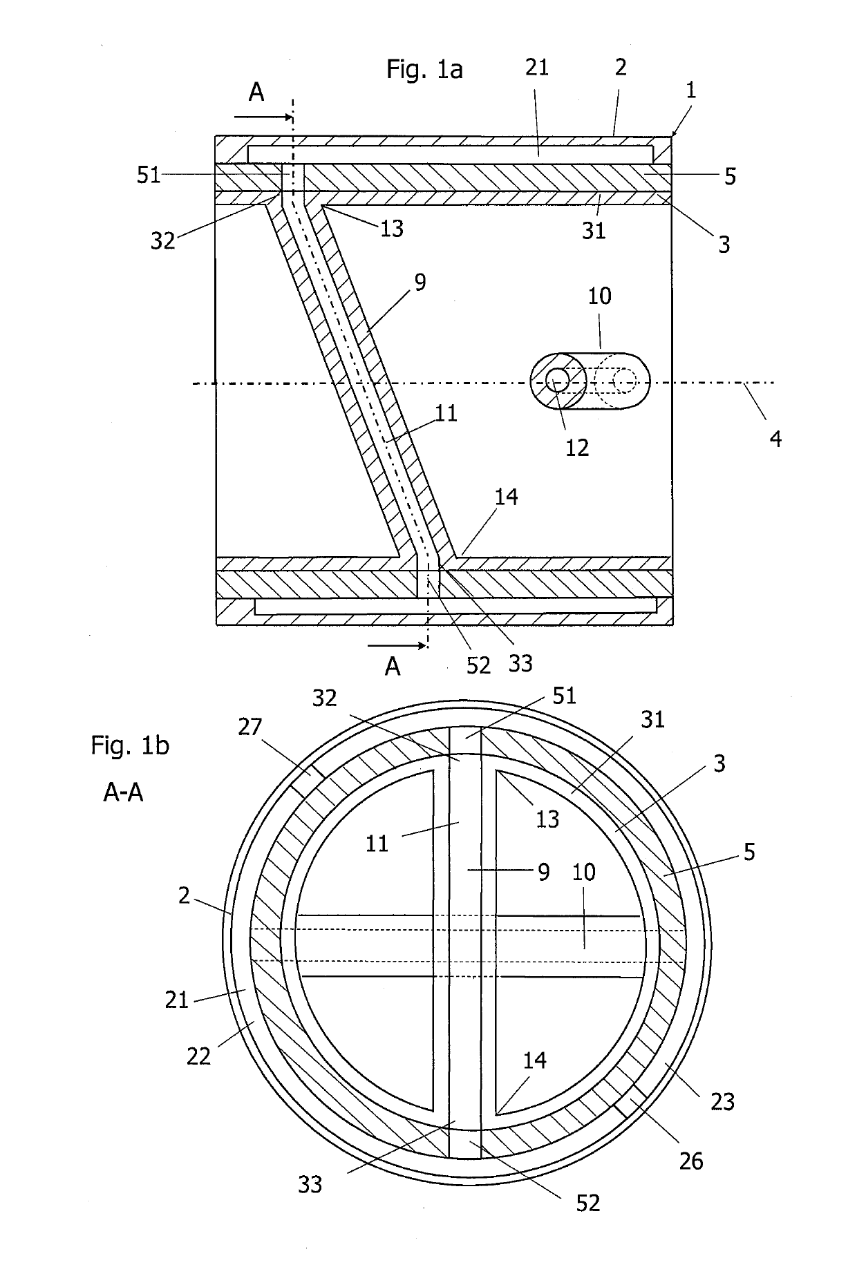
[0066]FIG. 1a shows a longitudinal section through a heat exchanger according to a The heat exchanger 1 for static mixing and heat exchange according to FIG. 1a contains a jacket element 2 and an insert element 3, the insert element 3 being arranged in the interior of the jacket element 2 in the operating state. The jacket element 2 is designed as a hollow body. The insert element is received in the hollow body. The insert element 3 has a longitudinal axis 4, which extends essentially in the main flow direction of the flowable medium, which flows through the jacket element 2 in the operating state. The insert element 3 contains an insert jacket element 31 and at least one web element 9, 10. The web element 9, 10 has a first end 13 and a second end 14, the first end 13 and the second end 14 of the web element 9, 10 is connected to the insert jacket element 31 at different locations. The web element 9, 10 contains a web element channel 11, 12. The web element channel 11, 12 extends f...

second embodiment

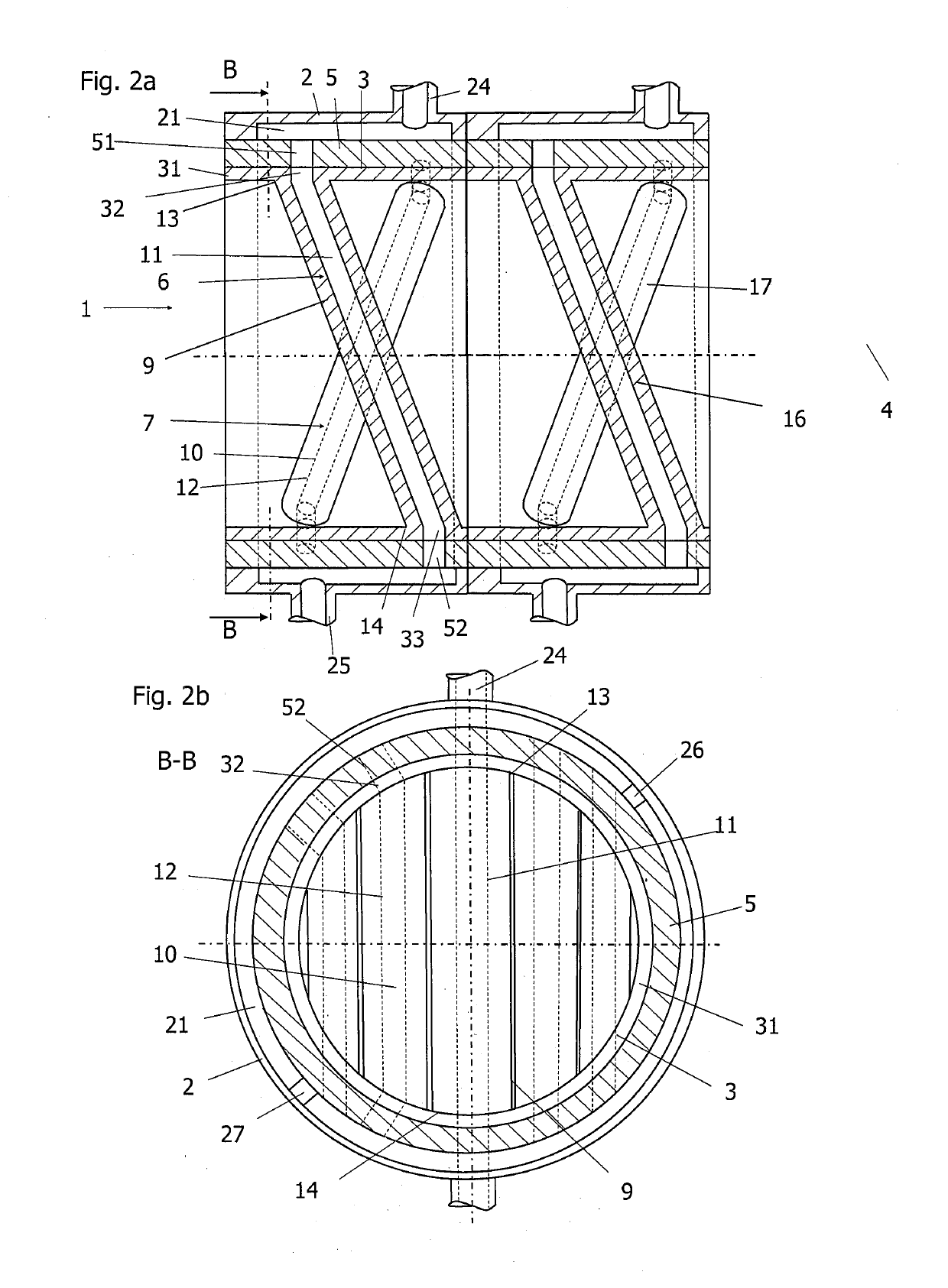
[0072]FIG. 2a shows a longitudinal section through a heat exchanger 1 according to a The heat exchanger 1 comprises an insert element 3, an intermediate jacket element 5 and a jacket element 2. The insert element 3 comprises a first and second group 6, 7 of web elements 9, 10 fixed to a non-zero angle with respect to the main flow direction and fixedly connected to at least a part of web elements 9, 10 connected insert jacket element 31. The web elements 9, 10 include web element channels 11, 12. These web element channels 11, 12 are flowed through in the operating state by a heat transfer fluid. The heat transfer fluid is not in communication with the flowable medium, which flows around the web elements 9, 10, FIG. 2a shows a first insert element 3 and a second insert element 3, which have the same structure. For each of the first and second insert elements 3, an intermediate jacket element 5 and a jacket element 2 can each be provided. Alternatively, each of the first and second ...

fourth embodiment

[0093]FIG. 4a shows a longitudinal section through a heat exchanger 1 according to a The web elements 9, 10 of the insert element 3 are arranged substantially in the radial direction, that is, the longitudinal axis of the web elements 9, 10 extends at an angle of 90 degrees to the longitudinal axis 4. The web elements 9, 10 may have a circular or oval cross-section.


PUM

PropertyMeasurementUnit
thicknessesaaaaaaaaaa
temperaturesaaaaaaaaaa
pressuresaaaaaaaaaa

Abstract

The heat exchanger (1) contains a jacket element (2) and an insert element (3), wherein the insert element (3) is arranged in the operating state in the interior of the jacket element (2). The insert element has a longitudinal axis (4). The insert element (3) contains an insert jacket element (31) and a plurality of web elements (9, 10), the web elements (9, 10) having a first end (13) and a second end (14). The first end (13) and the second end (14) of each web element (9, 10) are connected to the insert jacket element (31) at different locations. At least a portion of the web elements (9, 10) includes web element channels (11, 12), the web element channels (11, 12) extending from the first end (13) of the web element (11) to the second end (14) of the web element (11). An intermediate jacket element (5) is arranged between the insert jacket element (31) and the jacket element (2).

Description

TECHNICAL FIELD[0001]The invention relates to a heat exchanger, which can be manufactured economically, which can be used also as static mixer or a static mixer, which can also be configured as a heat exchanger at the same time or can include the function of a heat exchanger. The heat exchanger is particularly suitable for cooling or heating flowable media, such as fluids, wherein the fluids may include, for example, viscous or highly viscous fluids, in particular polymers.[0002]Heat exchangers are used in many areas of the processing industry. According to an embodiment, a flowable medium can be moved over at least one stationary insert element. The insert element usually contains built-in elements, which cause a deflection of the fluid flow or of the flowable medium, which is guided through the interior of the insert element, which is bounded by an insert jacket element. A heat transfer fluid flows through the built-in elements. The flowable medium flows through the insert element...

Claims


Application Information

Patent Timeline
Patent Type & Authority Applications(United States)
IPC IPC(8): F28F13/12B01F23/47
CPCF28F13/12F28F2210/10F28D7/0058F28F1/003F28D2021/0052B01F23/47B01F25/4319B01F25/431B01F25/431974B01F35/93
Inventor HEUSSER, ROLF
Owner PROMIX SOLUTIONS
Why Eureka
Try Eureka