Ultrasonic position detection system

Inactive Publication Date: 2019-05-30
FIDELITY TECH
View PDF0 Cites 0 Cited by
  • Summary
  • Abstract
  • Description
  • Claims
  • Application Information

AI Technical Summary

Benefits of technology

[0012]The present invention may incorporate a resonant receiver which only detects a specific frequency of ultrasonic tone (for example 40 KHz). This creates a natural band pass filter, thus avoiding problems with more typical “time of flight” systems with overload or false signals due to extraneous noise.
[0013]The present invention allows situations in which only one portable device transmits a single ultrasonic tone at a time to one sensory array, thus avoiding problems present in “time of flight” systems due to interference making d

Problems solved by technology

Problems exist with ultrasonic time-of-flight tracking systems.
This is a tedious task and not conducive to an immersive simulation system.
Another problem is that many time-of-flight portable entities are configured with microphones to detect the ultrasonic transmission.
Microphones are susceptible to outside noise.
They can overload or trigger false signals due to outside noise.
Time-o

Method used


Image

  • Ultrasonic position detection system
  • Ultrasonic position detection system
  • Ultrasonic position detection system

Examples


Example

[0053]For both the X and the Y axis calculations, the phase differentials for example are phase angle calculations. In this case, the phase angle differential is calculated and used to determine the angle of arrival of the signal, thereby allowing for determination of X and Y positions. The phase angle is the change (horizontal shift) between the samplings of the X or Y axis sensors and the reference sensor or the phase angle differential.

DETAILED DESCRIPTION OF THE INVENTION

[0054]The instant system is described in further detail with respect to the enclosed Figures. The following detailed description of the Figures enclosed herewith further illustrate the invention but should not be construed as in any way limiting its scope.

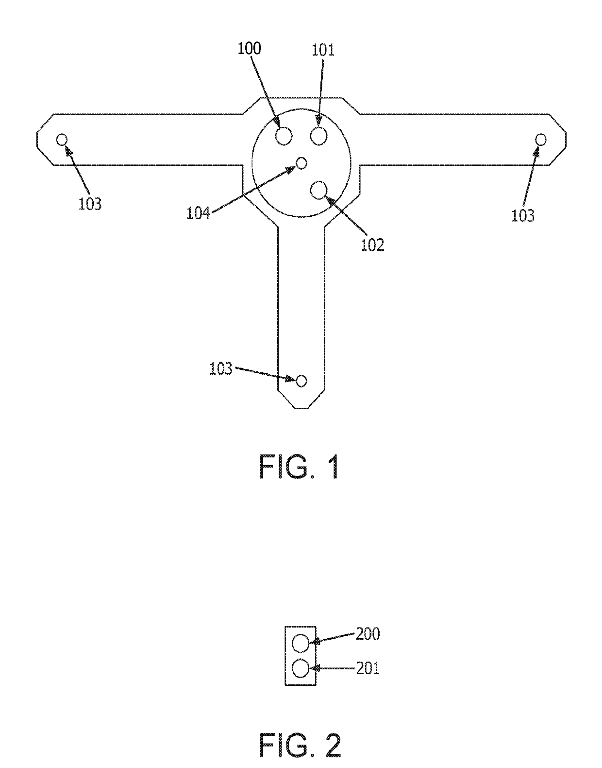
[0055]FIG. 1 illustrates an exemplary configuration of the present invention. Sensors are arranged in a pattern so as to allow a measured time difference between the arrival of an ultrasonic tone to the X axis sensor (100) and a Reference sensor (101), and a me...


PUM


Abstract

Tracking systems have been successfully applied to immersive simulation systems and virtual environment training in which portable devices (i.e., hand-held military equipment) within the immersive simulation system are tracked using time-of-fright recordings to triangulate each devices position. Until now, tracking systems have not used differential calculations to track these portable devices. The invention uses a single array of sensors mounted above the simulation area to communicate with small transmitters and emitters mounted on each portable device to generate position offsets for each portable device.

Description

FIELD OF THE INVENTION[0001]Described herein are position detection (tracking) systems, and in particular ultrasonic position detection systems that utilize at least one stationary array-based ultrasonic receiver in combination with a portable ultrasonic transmitter to be tracked to provide a safe and robust position detection system.BACKGROUND OF THE INVENTION[0002]This invention relates to a position tracking system. In an exemplary embodiment, the invention relates to an immersive simulation system which incorporates the position tracking system. More particularly, the invention relates to an immersive military simulation system which incorporates the position tracking system.[0003]Most current ultrasonic tracking systems use “time-of-flight” from a series of stationary ultrasonic transmitters strategically placed around an area of interest and received by one or more portable devices in order to calculate the portable devices' positions. In a time of flight system, a portable de...

Claims


Application Information

Patent Timeline
IPC IPC(8): G01S11/14G01S3/801G01S3/86G03B21/14H04N9/31
CPCG01S11/14G01S3/801G01S3/86G03B21/14H04N9/3147G01S19/22G01S5/30G01S11/16
Inventor CHAYKA, STANLEY JOSEPHHUBER, ERIC ALAN
Owner FIDELITY TECH
Why Eureka
Try Eureka