
Conductive pattern, display device including the same, and method of manufacturing conductive pattern

a display device and pattern technology, applied in the direction of instruments, optics, basic electric elements, etc., can solve the problems of signal delay, deterioration of display quality, increased wiring, etc., and achieve excellent reliability and excellent reliability

Active Publication Date: 2019-05-30
SAMSUNG DISPLAY CO LTD
View PDF0 Cites 3 Cited by
  • Summary
  • Abstract
  • Description
  • Claims
  • Application Information

AI Technical Summary

Benefits of technology

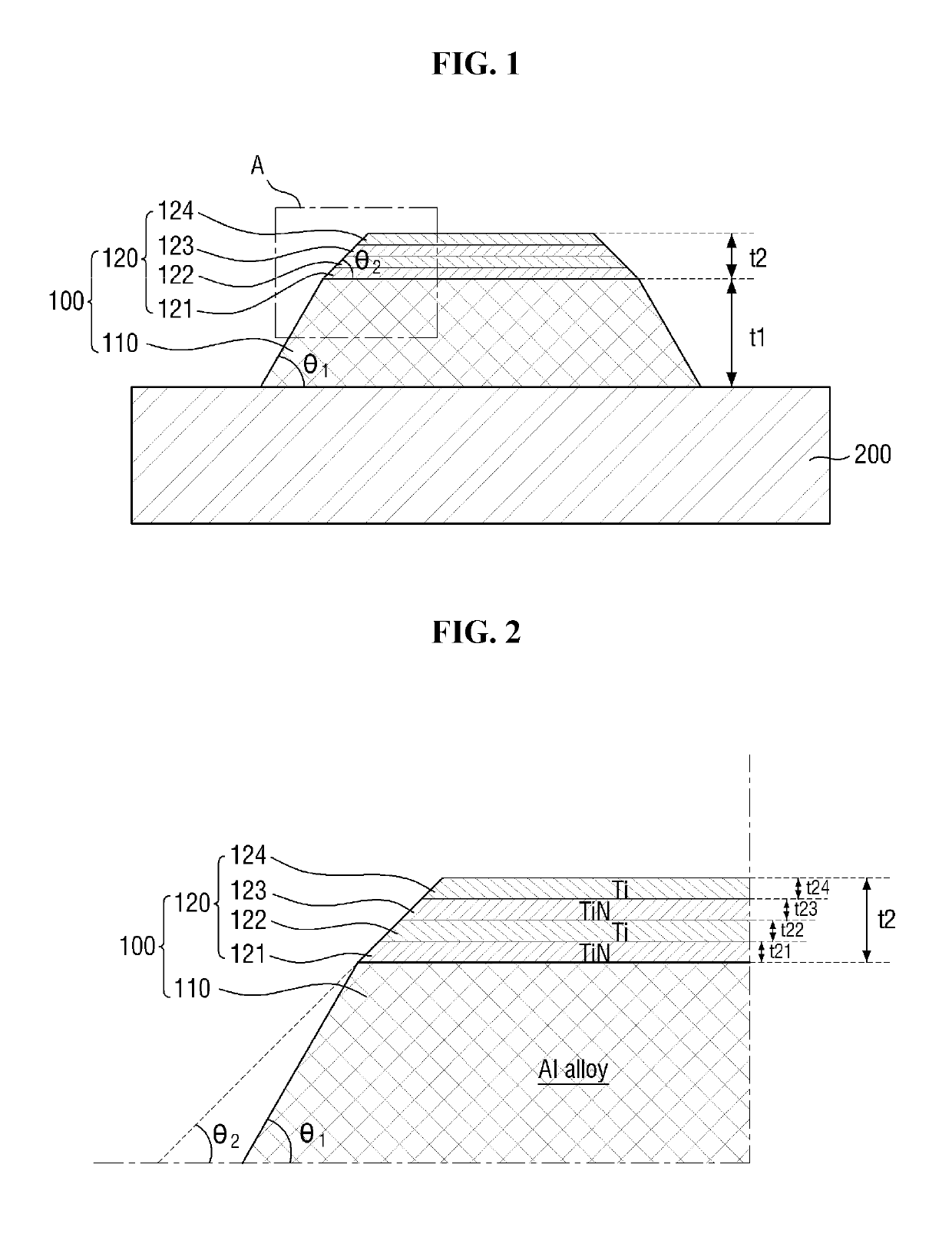
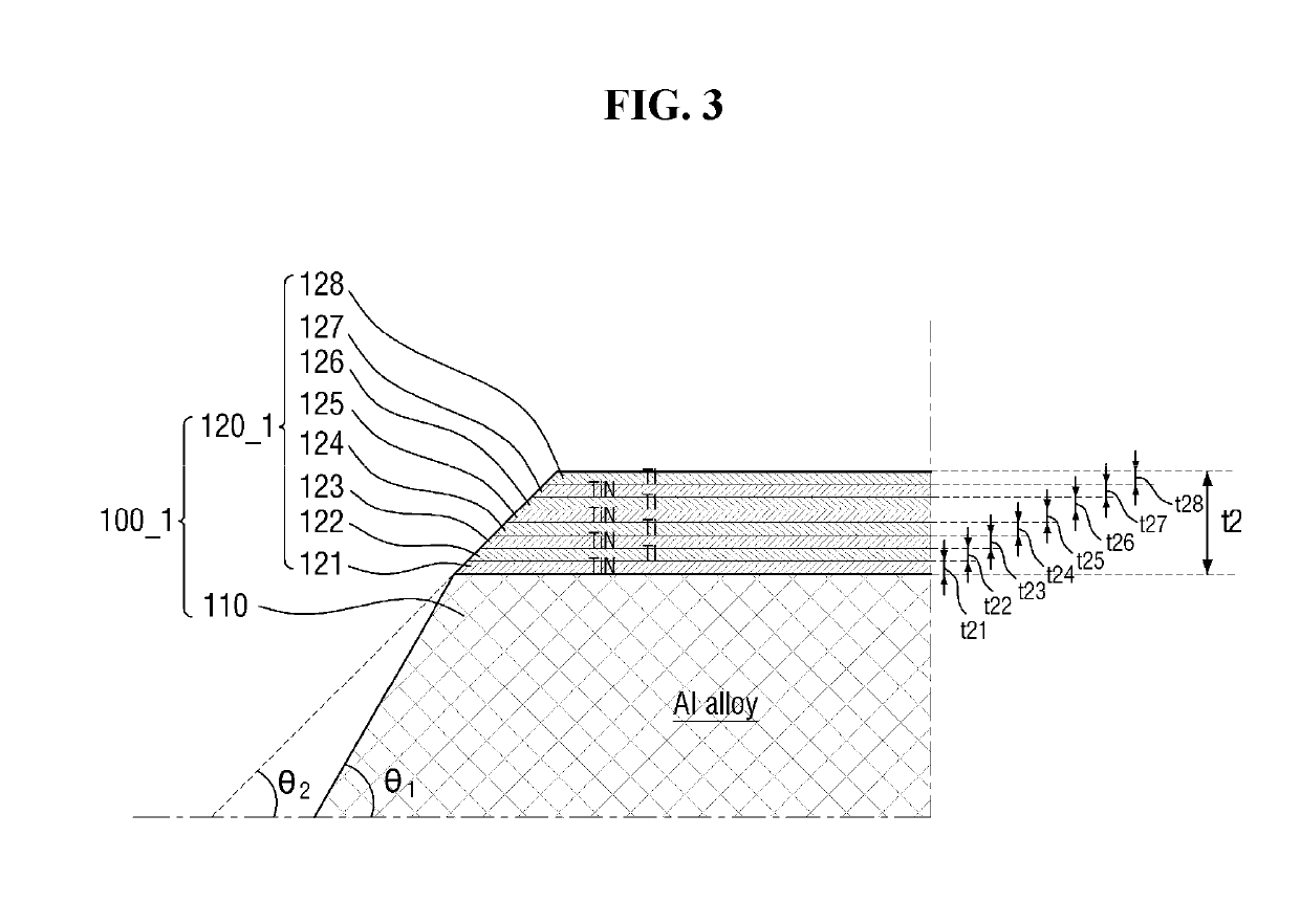
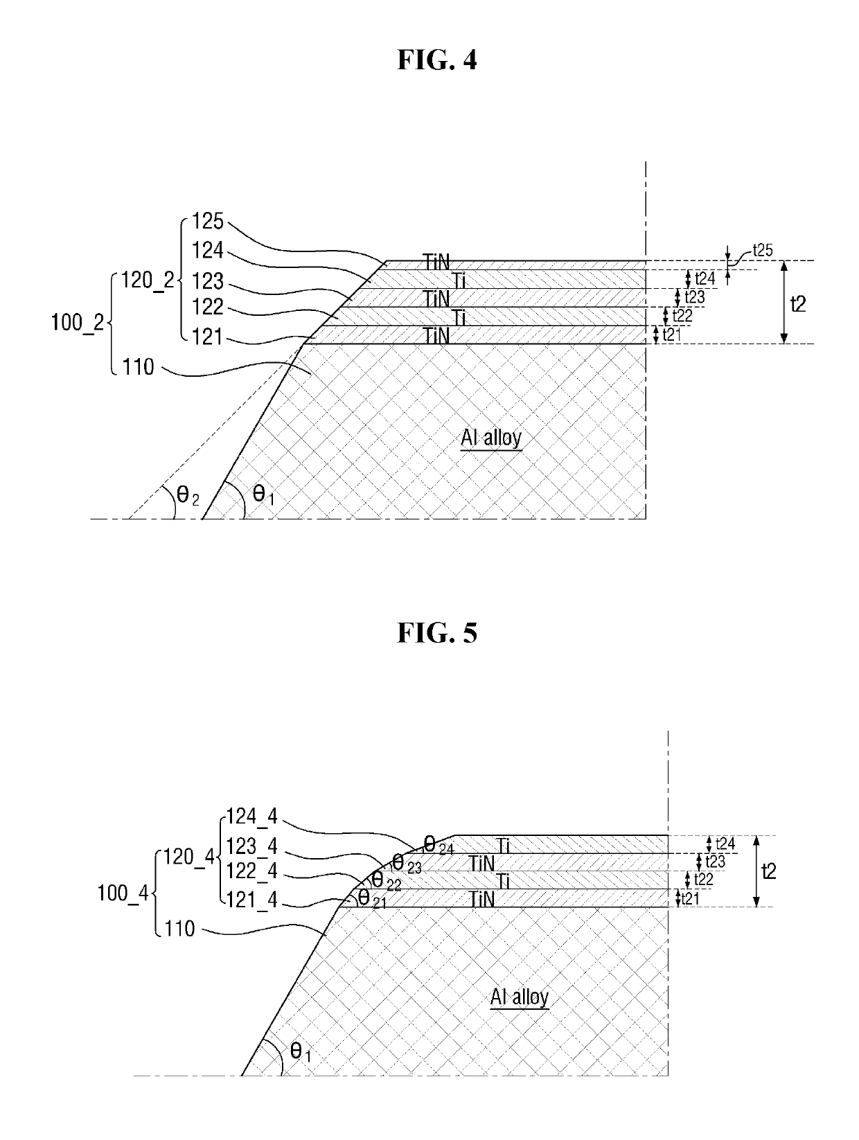
The invention provides a display device with a low-resistance conductive pattern that has reliable and efficient performance. The capping layer, made of multiple layers, including a titanium nitride layer, prevents the diffusion of metal components and protects the main conductive layer during a cleaning process. The small taper angle of the capping layer allows for better filling of insulating material in the side surface of the conductive pattern, improving the film quality of the insulating film. When a conductive pattern with a low-resistance material, such as aluminum or aluminum alloy, is used in display devices, signal delay is reduced and display quality is improved.

Problems solved by technology

When the length of a signal wiring is increased, however, a signal delay may occur due to the internal resistance of the signal wiring.
Delay of a scanning signal in a high-resolution display device may deteriorate display quality due to difficulties in securing a sufficient gate-on time.
However, signal wirings may be exposed to various environments during manufacture.
For example, an annealing process, an etching process, or the like may cause damage to the material of the signal wiring.
As such, even when the signal wiring includes a low-resistance material well known in the art, it is generally difficult to secure process reliability when the low-resistance material is directly used as a conductive pattern.

Method used


Image

  • Conductive pattern, display device including the same, and method of manufacturing conductive pattern
  • Conductive pattern, display device including the same, and method of manufacturing conductive pattern
  • Conductive pattern, display device including the same, and method of manufacturing conductive pattern

Examples


Embodiment Construction

[0045]In the following description, for the purposes of explanation, numerous specific details are set forth in order to provide a thorough understanding of various exemplary embodiments or implementations of the invention. As used herein “embodiments” and “implementations” are interchangeable words that are non-limiting examples of devices or methods employing one or more of the inventive concepts disclosed herein. It is apparent, however, that various exemplary embodiments may be practiced without these specific details or with one or more equivalent arrangements. In other instances, well-known structures and devices are shown in block diagram form in order to avoid unnecessarily obscuring various exemplary embodiments. Further, various exemplary embodiments may be different, but do not have to be exclusive. For example, specific shapes, configurations, and characteristics of an exemplary embodiment may be used or implemented in another exemplary embodiment without departing from ...


PUM


Abstract

A conductive pattern for a display device includes a first layer including aluminum or an aluminum alloy disposed on a substrate and forming a first taper angle with the substrate, and a second layer disposed on the first layer forming a second taper angle with the first layer, in which the second taper angle is smaller than the first taper angle.

Description

CROSS-REFERENCE TO RELATED APPLICATION[0001]This application claims priority from and the benefit of Korean Patent Application No. 10-2017-0160172, filed on Nov. 28, 2017, which is hereby incorporated by reference for all purposes as if fully set forth herein.BACKGROUNDField[0002]Exemplary implementations of the invention relate generally to a conductive pattern, a display device including the same, and a method of manufacturing a conductive pattern.Discussion of the Background[0003]Electronic devices generally employ a conductive pattern, such as wirings or electrodes, to transmit signals. For example, a display device, such as an organic light emitting display device or a liquid crystal display device, may include a plurality of conductive patterns for driving a thin film transistor (TFT). When the length of a signal wiring is increased, however, a signal delay may occur due to the internal resistance of the signal wiring. Delay of a scanning signal in a high-resolution display de...

Claims


Application Information

Patent Timeline
IPC IPC(8): H01L27/32H01L51/56
CPCH01L27/3279H01L51/56H01L23/5283H01L23/53223H01L27/1244G02F1/13629H10K71/00H10K71/621H01L21/0274H10K59/1213H10K71/20H10K59/1315
Inventor LEE, JOON GEOLKO, KYEONG SUSHIN, SANG WONLEE, DONG MINKIM, SANG GABSOHN, SANG WOOSHIN, HYUN EOKCHOI, SHIN IL
Owner SAMSUNG DISPLAY CO LTD
Learn More