Emu impulse antenna

a technology of impulse antenna and subsurface structure, which is applied in the field of electromagnetic surveying of subsurface structures, can solve the problems of difficult transmission of crisp high-current pulses, difficulty in transferring wavelength to antenna size ratio, and difficulty in transferring high-current pulses. , to achieve the effect of high instantaneous power output, small aperture and high power

Active Publication Date: 2019-06-06
SAUDI ARABIAN OIL CO
View PDF12 Cites 0 Cited by
  • Summary
  • Abstract
  • Description
  • Claims
  • Application Information

AI Technical Summary

Benefits of technology

[0005]Embodiments of this disclosure combines a slow-wave antenna with energy storage and pulse forming elements to realize a high power, small aperture transmitting antenna that is ideally suited for downhole electromagnetic interrogation technologies, such as for electromagnetic imaging of a subsurface hydrocarbon reservoir. Systems and methods described herein provide a transmitter that is compact, very high in instantaneous power output and generates a very clean signal.
[0006]Embodiments of this disclosure provide a dipole antenna that both increases radiation resistance and transmitter efficiency. The length of the antenna is shorter than some current antennas because the dipole antenna components are loaded with materials with relatively high dielectric permittivity (e), magnetic permeability (mu), or a combination of dielectric permittivity and magnetic permeability. The material can be selected so that e and mu of such material optimizes transmitter impedance to match the external medium. This increases the capacitance and inductance of the system and decreases the group velocity of the signal traveling along the antenna element, and can materially decrease the length of the antenna structure for a given wavelength emitted.
[0007]In addition, the antenna elements of embodiments of this disclosure are used as capacitive energy storage elements, with each half of the dipole initially held at a high voltage relative to one another. A fast-closing switch, such as a triggered spark gap, is provided between a pair of such antennas to initiate pulsed transmission. The pair of antennas is biased apart by a large voltage so that the structure can discharge in a single massive current pulse and emit a very high power transient radio frequency signal. Systems and methods of this disclosure therefore combine energy storage, pulse formation and radiating elements into a single structure, eliminating the need for impedance matching between separate distributed components for these respective functions.
[0008]Systems and methods of this disclosure eliminate the problem of load matching between a power supply, cable or transmission-line and antenna. With the energy storage element and switch inside the transmitting antenna element, the cable between the two is eliminated, minimizing reflections and losses in the system.

Problems solved by technology

The apparent ‘aperture’ of the antenna (wavelength to antenna size ratio) can be problematic.
However, these systems have been shown to have difficulty transferring a crisp high-current pulse from the power supply, down a low-loss cable, and then matching that into the antenna and in addition, the high-current cabling can also transmit a signal, which made the resulting measurements unclear.

Method used


Image

  • Emu impulse antenna
  • Emu impulse antenna
  • Emu impulse antenna

Examples


Embodiment Construction

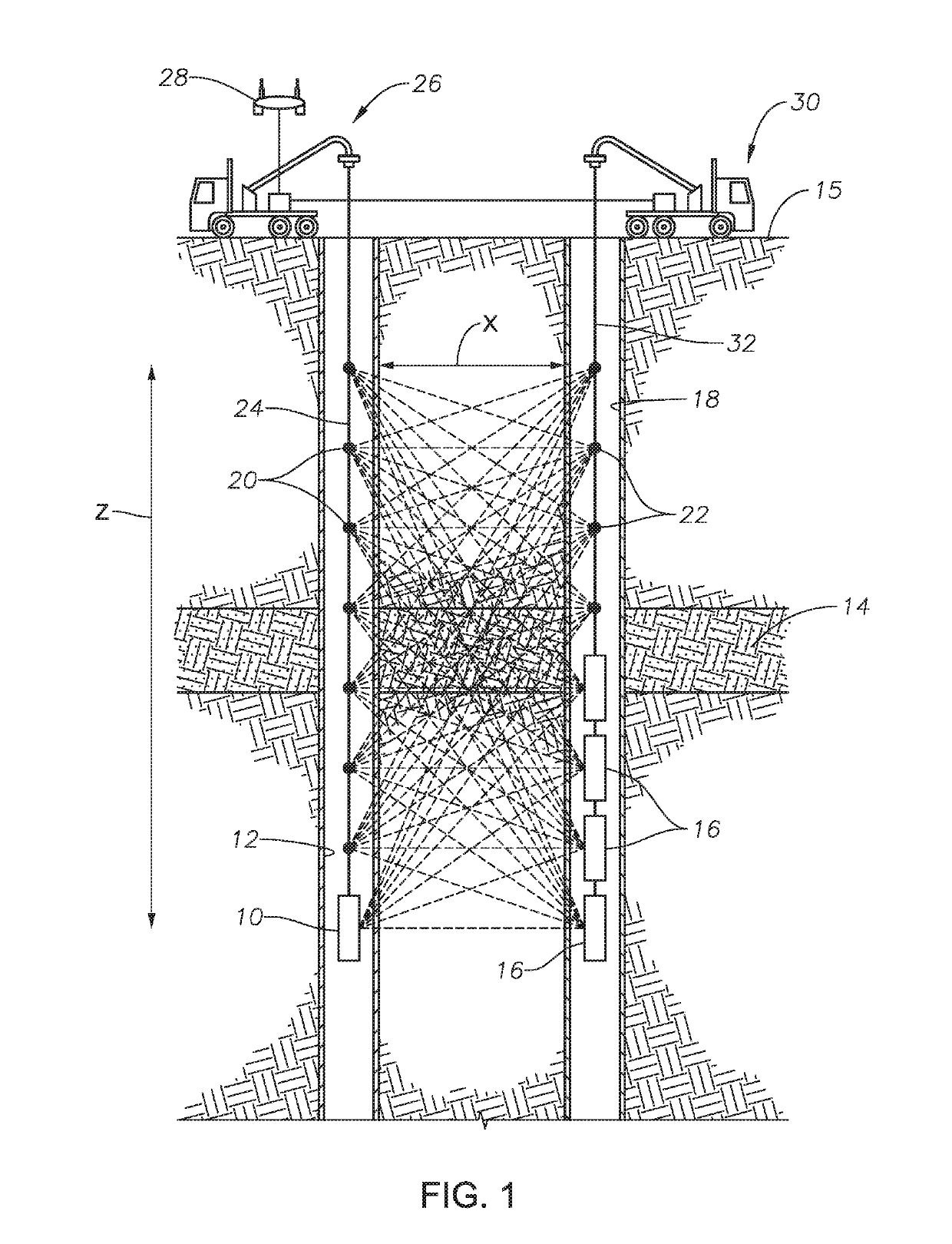
[0030]Looking at FIG. 1, an example arrangement of a transmitter-receiver array for a borehole to borehole electromagnetic survey is shown. The transmitter can be electromagnetic energy source 10. Electromagnetic energy source 10 can be located within well borehole 12. Well borehole 12 can extend through subsurface hydrocarbon reservoir 14. Electromagnetic energy source 10 can emit pulses of electromagnetic energy to travel through subsurface hydrocarbon reservoir 14 for electromagnetic imaging of subsurface hydrocarbon reservoir 14.

[0031]Although one electromagnetic energy source 10 is shown in the example of FIG. 1, in alternate embodiments, multiple electromagnetic energy sources 10 can be located within borehole 12. Alternately, one or more electromagnetic energy sources 10 can be located at the earth surface 15 above the subsurface hydrocarbon reservoir. In the example of FIG. 1, a series of electromagnetic sensors 16 are located in sensor bore 18. Sensor bore 18 can be a boreh...


PUM


Abstract

An electromagnetic energy source for emitting pulses of electromagnetic energy includes a sonde assembly having a first section axially aligned with, and spaced from, a second section. An energy storage capacitor of the sonde assembly includes an electrode mounted in each of the first section and the second section of the sonde assembly and operable to generate an electric field, and a capacitive charge storage medium mounted in each of the first section and the second section of the sonde assembly and surrounding each electrode. The sonde assembly further includes a fast-closing switch located between the electrodes of the first and second sections of the sonde assembly.

Description

CROSS REFERENCE TO RELATED APPLICATION[0001]This application is a continuation of, and claims priority to and the benefit of, co-pending U.S. application Ser. No. 15 / 458,772, filed Mar. 14, 2017, titled “EMU Impulse Antenna,” the full disclosure of which is hereby incorporated herein by reference in its entirety for all purposes.BACKGROUND OF THE INVENTION1. Field of the Invention[0002]The present invention relates to imaging sub-surface structures, particularly hydrocarbon reservoirs and fluids therein, and more particularly to electromagnetic energy sources for electromagnetic surveying of sub-surface structures.2. Description of the Related Art[0003]Some electromagnetic (EM) surveying systems used in geophysics provide electromagnetic energy for traveling through a subsurface hydrocarbon reservoir for electromagnetic imaging of the subsurface hydrocarbon reservoir. Multiple sources and receivers can be positioned either in a bore that extends to the subsurface hydrocarbon reservo...

Claims


Application Information

Patent Timeline
Patent Type & Authority Applications(United States)
IPC IPC(8): G01V3/02G01V3/30G01V3/20
CPCG01V3/02G01V3/30G01V3/20G01V2003/084
Inventor SCHMIDT, HOWARD K.FELIX SERVIN, JESUS MANUELELLIS, ERIKAKANJ, MAZEN Y.AL-SHEHRI, ABDULLAH AWADH
Owner SAUDI ARABIAN OIL CO
Why Eureka
Try Eureka