
Indirect luminaire

a direct luminaire and indirect technology, applied in the field of indirect luminaires, can solve the problems of their own drawbacks, and not being able to achieve satisfactory unified glare ratings

Active Publication Date: 2019-06-06
SIGNIFY HLDG BV
View PDF15 Cites 2 Cited by
  • Summary
  • Abstract
  • Description
  • Claims
  • Application Information

AI Technical Summary

Benefits of technology

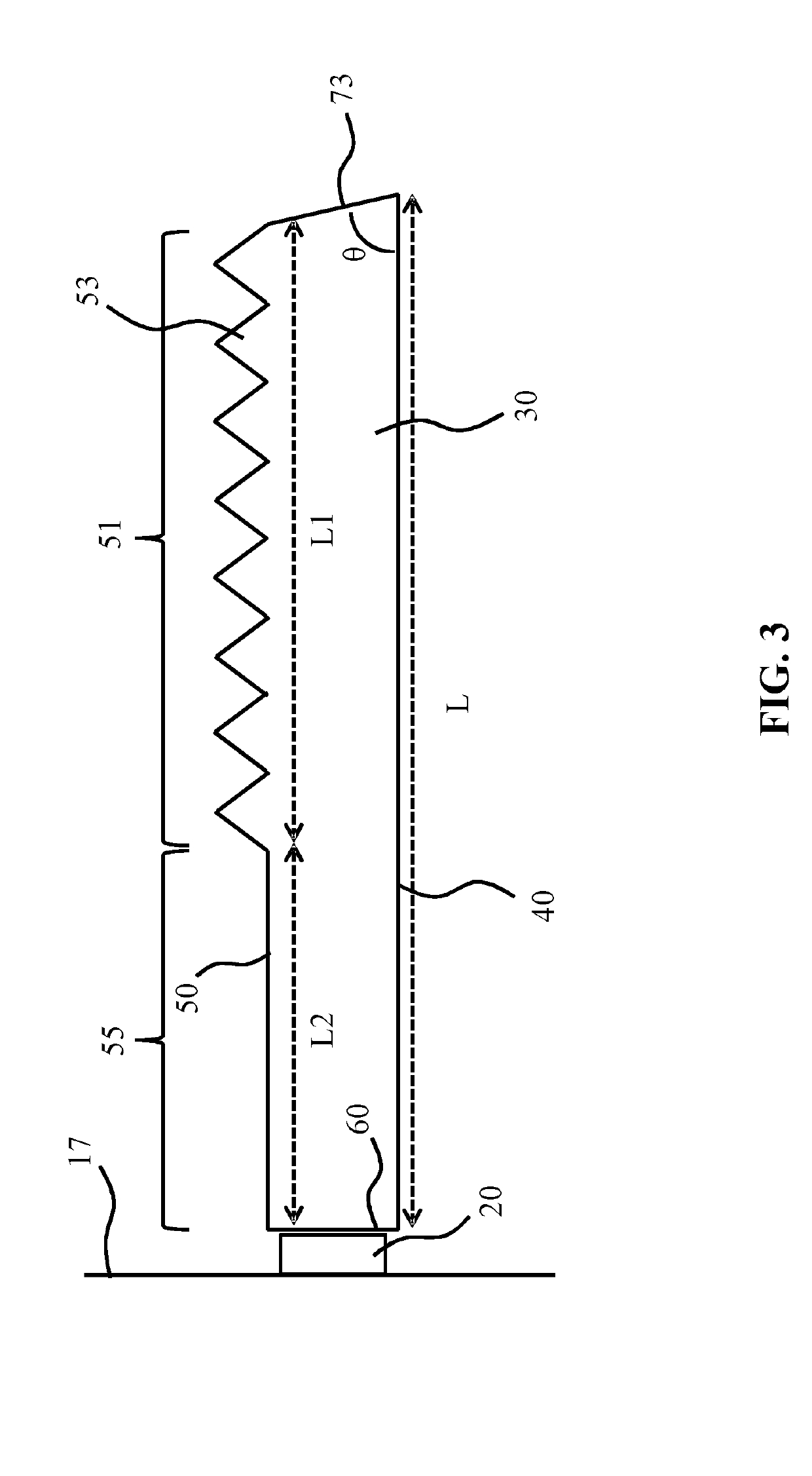
The patent text describes a lighting system that ensures even distribution of light from a light source to different regions of a curved reflective surface. This is achieved by using a light guide with prisms that distribute the light to the reflective surface. The system also includes a further edge surface with a slanted surface portion that improves the efficiency of the light guide by reflecting incident light rays towards the reflective surface. The distance between the light guide and the reflective surface is set to be substantial, which reduces energy loss and improves optical efficiency. The technical effects of the patent text are improved homogeneity of luminous output and excellent beam characteristics with the lighting system.

Problems solved by technology

Nevertheless, market penetration of such SSL devices is not without challenges.
A more serious challenge is to produce a luminous output with an SSL device that closely resembles the luminous output distribution of an equivalent traditional light source.
However, such solutions each have their own drawbacks.
Such an arrangement is therefore less suitable to achieve a satisfactory unified glare rating (UGR) due to the poor control over the beam angle produced by such luminaires.
A reflector-based solution works rather well if the overall size of the luminaire is relatively modest, but becomes less satisfactory, e.g. in terms of homogeneity of the luminous output, if the width of the luminaire increases, i.e. in the direction of the optical axis of the SSL elements.
This is because the SSL elements need to project their luminous outputs over greater distances such that the regions of the curved reflector distal to the SSL elements become underexposed to the luminous output, causing a dimming effect in the luminous output of the luminaire in its periphery.
As will be understood from the foregoing, such an arrangement suffers from poor control over the beam shape produced with the luminaire due to the presence of the diffuser.
In addition, it is not straightforward to achieve a compact design (limited thickness) of such an arrangement due to the stacking of the SSL elements, lenses and diffuser in the thickness direction.
Such an illumination system is rather costly due to the large number of components it requires, e.g. the additional optical extractor, which further increases the form factor (e.g. thickness) of the illumination system.

Method used


Image

  • Indirect luminaire
  • Indirect luminaire
  • Indirect luminaire

Examples


Embodiment Construction

[0032]It should be understood that the Figures are merely schematic and are not drawn to scale. It should also be understood that the same reference numerals are used throughout the Figures to indicate the same or similar parts.

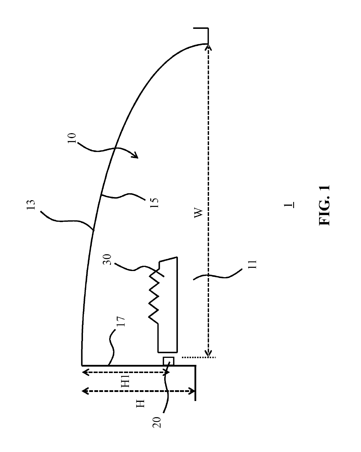
[0033]FIG. 1 schematically depicts a cross-sectional view of a luminaire 1 or part thereof, e.g. one half of such a luminaire 1. The luminaire 1 comprises at least one optical chamber 10 delimited by a light exit window 11 at the bottom of the optical chamber 10 in the orientation of the luminaire 1 as shown in FIG. 1. The light exit window 11 may be an open space or may be at least partially defined by a transparent or translucent body, e.g. a cover plate or the like, which may be made of any suitable material, e.g. glass or an optical grade polymer such as polycarbonate (PC), polyethylene terephthalate (PET), poly (methyl methacrylate) (PMMA) or any other suitable material. An upper region of the optical chamber 10 is delimited by a curved reflective surfac...


PUM


Abstract

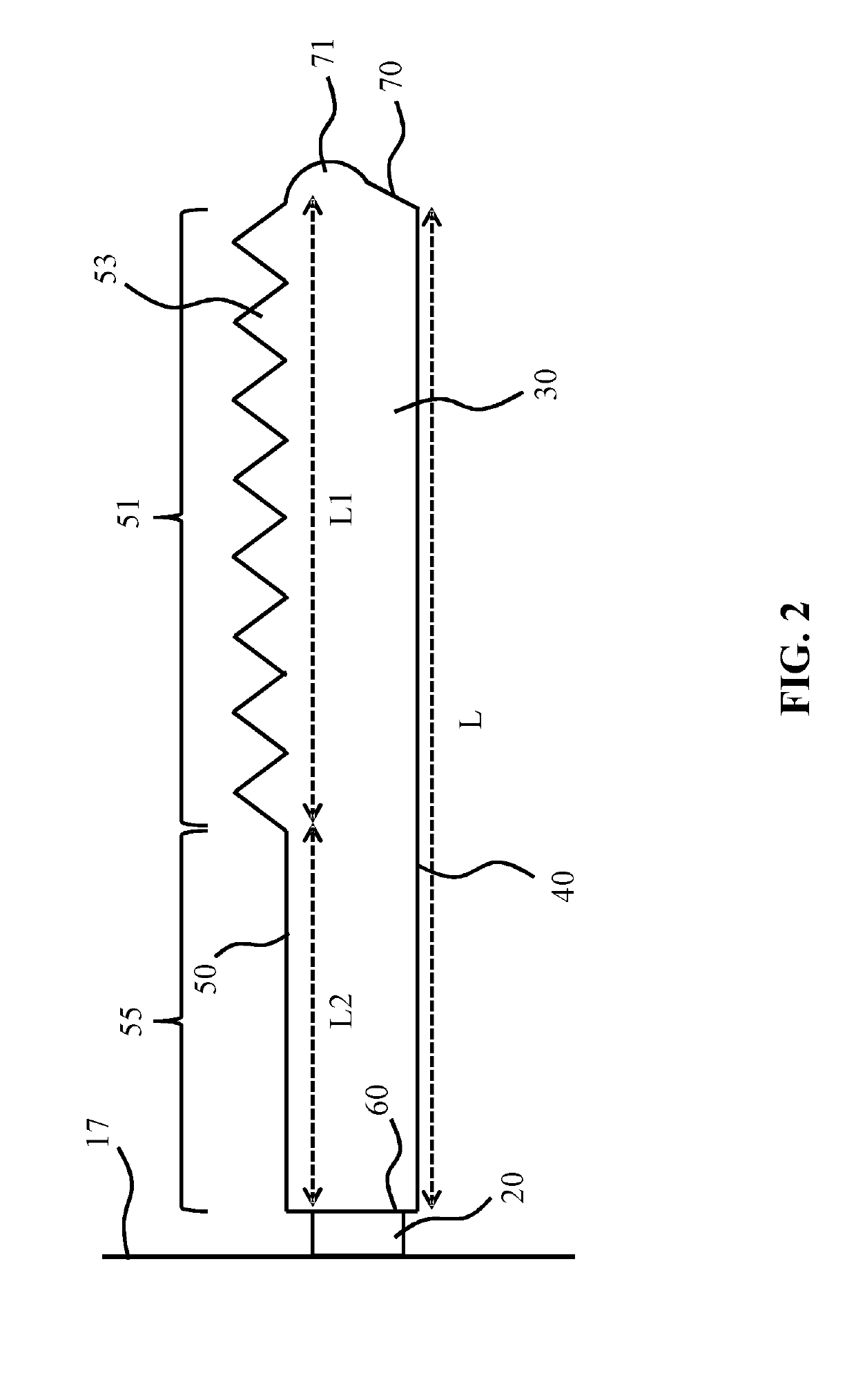
A luminaire (1) is disclosed comprising at least one optical chamber (10) delimited by a light exit window (11) and a curved reflective surface (15) extending from the light exit window to a mounting surface (17) extending from the curved reflective surface towards the light exit window. Each optical chamber comprises a light source (20) mounted on the mounting surface; and a light guide (30) extending across part of the optical chamber. The light guide comprises a total internal reflection major surface (40) facing the light exit window; a further major surface (50) facing the curved reflective surface, said further major surface comprising a light outcoupling portion (51) comprising a plurality of light outcoupling structures (53); a first edge surface (60) optically coupled to the light source; and a further edge surface (70) opposite the first edge surface arranged to direct light towards the curved reflective surface.

Description

FIELD OF THE INVENTION[0001]The present invention relates to a luminaire comprising at least one optical chamber delimited by a light exit window and a curved reflective surface extending from the light exit window to a mounting surface extending from the curved reflective surface towards the light exit window, each optical chamber comprising a light source mounted on the mounting surface.BACKGROUND OF THE INVENTION[0002]Solid state lighting (SSL), e.g. LED lighting, is rapidly gaining popularity because of its energy credentials and superior lifetime compared to traditional lighting, e.g. incandescent lighting, fluorescent lighting and halogen lighting. Nevertheless, market penetration of such SSL devices is not without challenges. For example, purchase cost of SSL devices is still higher than that of equivalent traditional light sources, even though the effective cost of such SSL devices is markedly lower due to their much longer lifetime, and this realisation by consumers is one ...

Claims


Application Information

Patent Timeline
IPC IPC(8): F21V8/00
CPCG02B6/0045G02B6/0055G02B6/0068G02B6/0088G02B6/0001
Inventor LI, QINLUO, QUNLI, KANGZHENG, ZHENYICHEN, MIN
Owner SIGNIFY HLDG BV
Learn More