Antenna module

a technology of antenna module and antenna, applied in the direction of antenna, antenna details, antenna earthing, etc., can solve the problems of output signal oscillation and noise in output signal

Active Publication Date: 2019-06-06
MURATA MFG CO LTD
View PDF0 Cites 10 Cited by
  • Summary
  • Abstract
  • Description
  • Claims
  • Application Information

AI Technical Summary

Benefits of technology

[0010]The present disclosure has been made to solve the problems described above. An object of the present disclosure is to improve, in an antenna

Problems solved by technology

This may cause noise in the output signal o

Method used


Image

  • Antenna module
  • Antenna module
  • Antenna module

Examples


Embodiment Construction

[0030]Embodiments of the present disclosure will now be described with reference to the drawings. In the following description, the same components are denoted by the same reference numerals, and their names and functions are also the same. The detailed description of the same components will therefore not be repeated.

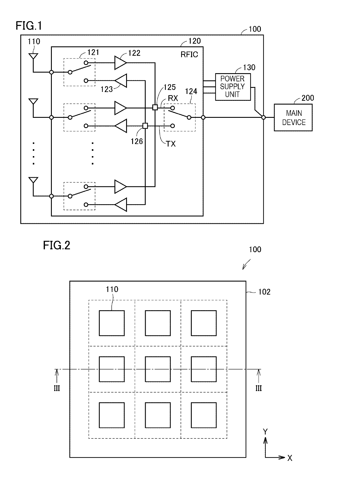
[0031]FIG. 1 is a functional block diagram for explaining the functions of an antenna module 100 according to the present embodiment. The antenna module 100 includes a plurality of antenna elements (hereinafter also simply referred to as “antennas”) 110, a radio frequency element (hereinafter also referred to as “radio frequency integrated circuit (RFIC)”) 120 connected to the antennas 110, and a power supply unit 130 configured to supply power to the RFIC 120. The antenna module 100 receives a signal transmitted from a main device 200 externally provided and radiates the signal from the antennas 110. Also, the antenna module 100 transmits a signal received by the ante...


PUM


Abstract

The present disclosure improves, in an antenna module, the isolation characteristic between an output signal from an antenna and an input signal. An antenna module includes a dielectric substrate having a first surface and a second surface, an antenna formed on the first surface, a radio frequency element configured to supply a radio frequency signal to the antenna, and a signal terminal formed into a columnar shape using a conductive material. The signal terminal is connected to the radio frequency element by a wiring pattern in the dielectric substrate. The signal terminal is disposed outside an excitation region generated in an excitation direction of an output signal.

Description

[0001]This is a continuation of International Application No. PCT / JP2017 / 020177 filed on May 31, 2017 which claims priority from Japanese Patent Application No. 2016-163496 filed on Aug. 24, 2016. The contents of these applications are incorporated herein by reference in their entireties.BACKGROUNDTechnical Field[0002]The present disclosure relates to an antenna module that includes a radio frequency element and an antenna element, and specifically relates to a technique for improving the isolation characteristic between an input signal to the radio frequency element and an output signal from the antenna element.[0003]For example, as disclosed in International Publication No. 2016 / 063759 (Patent Document 1) and International Publication No. 2016 / 067969 (Patent Document 2), an antenna module is known, which is formed as a module that combines an antenna element with a radio frequency element configured to supply a radio frequency signal to the antenna element.[0004]For connection to ...

Claims


Application Information

Patent Timeline
IPC IPC(8): H01Q1/52H01Q1/38H01Q23/00H01Q1/48H01Q9/04
CPCH01Q1/52H01Q1/38H01Q23/00H01Q1/48H01Q9/04H01Q1/2283H01Q3/24H01Q19/005H01Q21/065
Inventor ARIUMI, SANEAKI
Owner MURATA MFG CO LTD
Why Eureka
Try Eureka