Broadband ultrasound transducer

Active Publication Date: 2019-06-13
KONINKLJIJKE PHILIPS NV
View PDF0 Cites 11 Cited by
  • Summary
  • Abstract
  • Description
  • Claims
  • Application Information

AI Technical Summary

Benefits of technology

[0035]According to yet another aspect, there is provided a method of operating such an ultrasound imaging system, the method comprising applying, during an ultrasound transmission mode of the ultrasound imaging system, a control signal to the CMUT cells, the control signal comprising a DC component forcing the CMUT cells into a collapse mode and an AC com

Problems solved by technology

However, PZT suffers from a number of notable drawbacks.
Firstly, the ceramic PZT materials require manufacturing processes including dicing, matching layer bonding, fillers, electroplating and interconnections that are distinctly different and complex and require extensive handling, all of which can result in transducer stack unit yields that are lower than desired.
This manufacturing complexity increases the cost of the final transducer probe and puts design limitations on the minimum spacing between the elements as well as the size of the individual elements.
Moreover, PZT materials have a poorly matched impedance to water or biological tissue, such that matching layers need to be added to the PZT materials in order to obtain the desired acoustic impedance matching with the medium of interest.
As ultrasound system mainframes have become smaller and dominated by field programmable gate arrays (FPGAs) and software for much of the signal processing functionality, the cost of system mainframes has dropped with the size of the systems.
As a result, the cost of the transducer probe is an ever-increasing percentage of the overall cost of the system, an increase which has been accelerated by the advent of higher element-count arrays us

Method used


Image

  • Broadband ultrasound transducer
  • Broadband ultrasound transducer
  • Broadband ultrasound transducer

Examples


Embodiment Construction

[0053]It should be understood that the Figures are merely schematic and are not drawn to scale. It should also be understood that the same reference numerals are used throughout the Figures to indicate the same or similar parts.

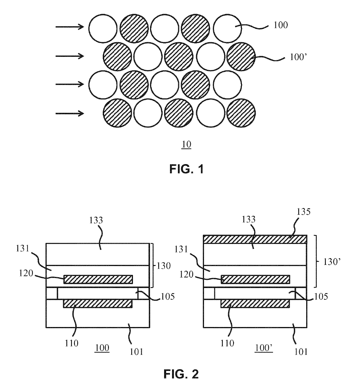
[0054]In the context of the present application, where reference is made to a membrane, this is a deformable structure that spans the gap or cavity over the substrate of a capacitive micromachined ultrasound transducer (CMUT), and that supports, e.g. embeds one of the electrodes of the CMUT, e.g. an electrode opposing a further electrode on the substrate and separated therefrom by a gap or cavity.

[0055]In the context of the present application, where reference is made to a membrane layer stack, this is intended to include membranes formed of a single layer as well as membranes formed of multiple layers, but excluding the electrode embedded in or otherwise supported by the membrane.

In the context of the present application, where reference is made to a CMUT el...


PUM


Abstract

A transducer array (10) is disclosed comprising a plurality of CMUT cells (100, 100, 100″), each CMUT cell comprising a first electrode (110) supported by a substrate (101) and a second electrode (120) supported by a membrane suspended over a cavity (105) between the first electrode and the second electrode, the plurality of CMUT cells comprising a first group of CMUT cells (100) each having a membrane comprising a first layer stack (130); and a second group of CMUT cells (100′) each having membrane comprising a second layer stack (130′), the second layer stack including a layer (135) of a material having a higher density than any of the layers in the first layer stack. Also disclosed is a device comprising such a transducer array, an ultrasound imaging system including such a transducer array and a method of operating such an ultrasound imaging system.

Description

FIELD OF THE INVENTION[0001]The present invention relates to a transducer array comprising a plurality of CMUT cells, each CMUT cell comprising a first electrode supported by a substrate and a second electrode supported by a membrane suspended over a cavity between the first electrode and the second electrode, the plurality of CMUT cells comprising a first group of CMUT cells and a second group of CMUT cells different to the first group of CMUT cells.[0002]The present invention further relates to a device comprising such a transducer array.[0003]The present invention still further relates to an ultrasound imaging system comprising such a transducer array.[0004]The present invention still further relates to a method of operating such an ultrasound imaging system.BACKGROUND OF THE INVENTION[0005]Ultrasonic transducers used for medical imaging have numerous characteristics that lead to the production of high quality diagnostic images. Among these are broad bandwidth, affecting resoluti...

Claims


Application Information

Patent Timeline
IPC IPC(8): B06B1/02G01N29/24G01S15/89A61B8/00
CPCB06B1/0292G01N29/2406G01S15/8925A61B8/4483G01N29/22
Inventor SHULEPOV, SERGEITIMMERMANS, PETRUS HENRICUS MARIADIRKSEN, PETER
Owner KONINKLJIJKE PHILIPS NV
Why Eureka
Try Eureka