Drill with improved cutting insert formation

a drilling insert and cutting technology, applied in the direction of cutting inserts, twist drills, manufacturing tools, etc., can solve the problems of difficulty in achieving high cutting speed, achieve high cutting speed, increase cutting speed, and maintain good life of drilling tools

Inactive Publication Date: 2004-03-04
SANDVIK INTELLECTUAL PROPERTY AB
View PDF26 Cites 14 Cited by
  • Summary
  • Abstract
  • Description
  • Claims
  • Application Information

AI Technical Summary

Benefits of technology

[0005] It is a second object of the invention to accomplish a new type if drill wherein the inserts have such optimized formation that high cutting speed becomes possible without impairing the surface finish of the hole wall in the hole to be drilled.
[0006] It is a third object to provide a drill wherein the drill inserts have been given such optimized formation that increased cutting speed becomes possible during drilling while maintaining good lifetime of the drilling tool.

Problems solved by technology

When designing drills of the abovementioned type there is often difficulty in achieving desired high cutting speeds since thermal cracks often appear at the active cutting corner where such thermal cracks usually appear.

Method used


Image

  • Drill with improved cutting insert formation
  • Drill with improved cutting insert formation
  • Drill with improved cutting insert formation

Examples


Embodiment Construction

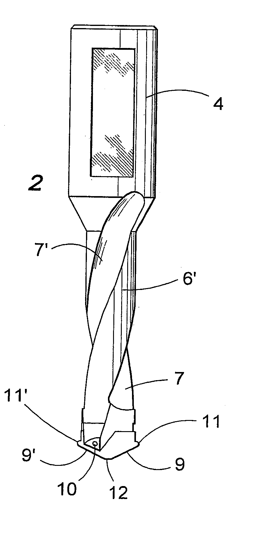
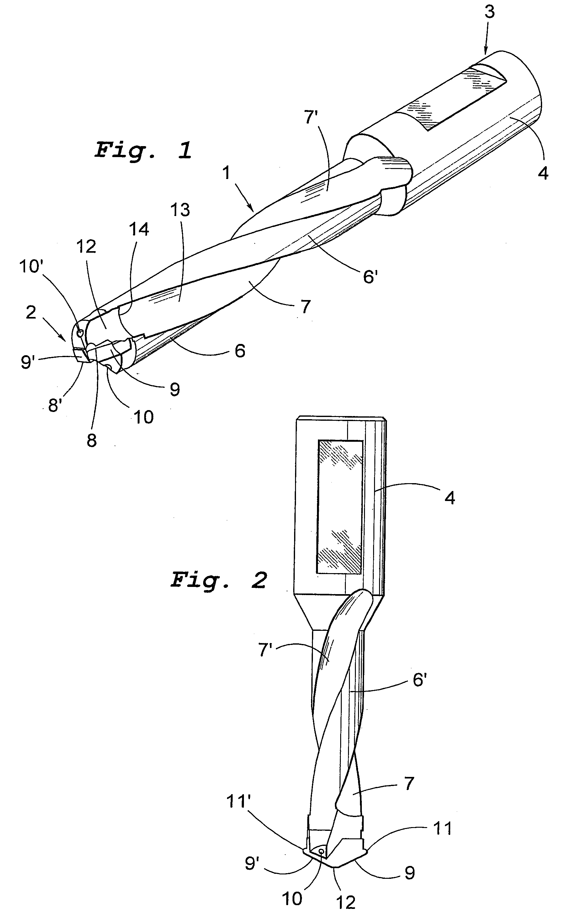
[0019] In the drawings 1 generally designates a solid shank of a suitable tool steel with a first end or tip 2 and an opposite second end 3. At this second, rear end the shank of the shown embodiment has a thicker part 4 suitable for insertion into a holder. From a core two lands 6, 6' protrude, which delimit two flutes 7, 7'. In the illustrated embodiment the drill is a twist drill on which the lands 6, 6' as well as the flutes 7, 7' extend helically around the longitudinal axis of the shank. In practice, these flutes in known manner have a suitably uniform pitch angle within the range 20-30.degree.. As alternative embodiments these flutes 7, 7' could be straight. At the tip 2, two cutting edges 8, 8' are provided, which in this case are formed on special cutting inserts 9, 9' that have been fixed to the tip in a suitable way, for instance by soldering. However, these cutting edges 8, 8' could equally well be formed by grinding of suitably formed surfaces on the shank per se or on ...


PUM

PropertyMeasurementUnit
pitch angleaaaaaaaaaa
rake angleaaaaaaaaaa
angleaaaaaaaaaa

Abstract

A drill comprising a tip-forming end including at least two cutting edges (8, 8') and at least two chip flutes (7, 7') extending from the tip end (2) towards the second end (3), having the purpose of forming and removing chips from the corresponding cutting edge. In accordance with the invention the drill tip is composed of cutting edges on mutual sides of the axial centre line having a straight unbroken contour, the central portions of which extend axially beyond the peripheral portions whilst the nose radiused surface on each cutting edge at the periphery is provided with a smoothly curved radius comprising one or several circular segments with mutually different radii (R1, R2, R3) where adjacent radii always appear with different size.

Description

[0001] The present invention relates to a drill comprising a substantially solid shank with a first tip-forming end including at least two cutting edges for cutting machining of metallic workpieces in order to make holes in these, an opposite second end, and a number of flutes corresponding to the number of cutting edges, extending from the tip end towards the other end, having the purpose of forming and removing chips from the corresponding cutting edge.BACKGROUND OF THE INVENTION AND DESCRIPTION OF THE PRIOR ART[0002] The flutes of, e.g., a twist drill, have two important functions, viz. on the one hand the forming of chips (including chipbreaking) and on the other hand the removal of these formed chips. The chip formation occurs in a space immediately behind each cutting edge, regardless of whether the edge is formed by a sharpening of the drill top as such, or by a separate cutting insert which is fastened on the tip, mechanically or, by, e.g., brazing. In this front space of a ...

Claims


Application Information

Patent Timeline
Patent Type & Authority Applications(United States)
IPC IPC(8): B23B51/00B23BB23B51/02B23B51/04
CPCB23B51/02B23B51/0493B23B2200/201Y10T408/909Y10S408/713Y10T408/9097Y10T408/78B23B2251/02B23B51/00B23B51/0004B23B2251/0825
Inventor EDVARDSSON, JANWIMAN, JORGENSJOLANDER, AKE
Owner SANDVIK INTELLECTUAL PROPERTY AB
Why Eureka
Try Eureka