
Valve stem structure and tire pressure monitoring system using the same

a valve stem and tire pressure monitoring technology, applied in the direction of tire measurement, vehicle components, transportation and packaging, etc., can solve the problems of increasing driver's expenses, inconvenience, extra expenditure, etc., and achieve the effect of saving unnecessary expenditures for consumers, improving user convenience, and reducing user's expenses

Active Publication Date: 2019-06-27
ONE UNIQUE INC
View PDF0 Cites 2 Cited by
  • Summary
  • Abstract
  • Description
  • Claims
  • Application Information

AI Technical Summary

Benefits of technology

The patent text describes a valve stem structure and a tire pressure monitoring system that use a conducting wire to supply power and communicate with each other. This allows for the battery to be remotely replaced without replacing the entire tire module, saving time, money, and environmental resources. The technical effects include improved user convenience, reduced expenses, and energy conservation.

Problems solved by technology

Consequently, the driver's expenses are increased, including the cost of the entire sub-module block (generally speaking, it is necessary to replace four blocks in total for a single operation of tire positioning), the expenses to remove the tire, install the sub-module block and reposition and calibrate the tires and so on.
The whole procedure is not only time-consuming but also causes inconvenience and extra expenditures.
At the same time, such configuration may also reduce the length of the passage of the tube, thereby avoiding the situation where the portion of the valve stem structure exposing out of the tire is too long and thus easily damaged during driving.

Method used


Image

  • Valve stem structure and tire pressure monitoring system using the same
  • Valve stem structure and tire pressure monitoring system using the same
  • Valve stem structure and tire pressure monitoring system using the same

Examples


first embodiment

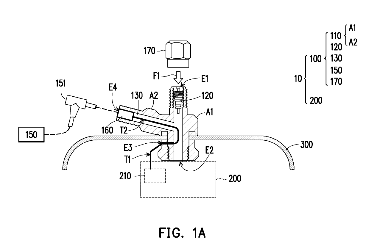
[0028]FIG. 1A is a schematic view showing a tire pressure monitoring system according to the disclosure. With reference to FIG. 1A, in this embodiment, a tire pressure monitoring system 10 includes a valve stem structure 100 and an electronic tire pressure monitoring device 200, wherein the electronic tire pressure monitoring device 200 is adapted to be disposed in a tire 300 and is fixed at a rim via the valve stem structure 100. The electronic tire pressure monitoring device 200 is a set of packaged electronic modules, and includes a pressure sensor, a radio frequency (RF) circuit board and a rechargeable battery cell 210 therein. The valve stem structure 100 is a self-contained valve device. When opened, the valve stem structure 100 allows a compressed air F1 to enter a tubeless tire or a space of an inner tube, and then automatically closes to seal the stored air to generate a pressure, thereby preventing the air from escaping out of the tire or the inner tube. Except for solid ...

second embodiment

[0033]FIG. 2 is a schematic view of a valve stem structure according to the disclosure, and this valve stem structure is applicable to the foregoing tire pressure monitoring system 10 as well. Different from the case of the previous embodiment, in a valve stem structure 400 here, a battery cell socket 420 is substantially disposed on a tube wall of a tube 410 and has a substantially uniform contour with an outer surface of the tube 410. An end T3 of a conducting wire 430, just like the first end T1 as described above, extends out of the tube 410 to be electrically connected to an electronic tire pressure monitoring device 200, and another end T4 of the conducting wire 430 is electrically connected to the battery cell socket 420. In this way, when a user joints an electrical connector (not shown) of a power source 150 to the battery cell socket 420 on the tube wall of the tube 410, an effect of power transmission may be achieved. Herein the battery cell socket 420 has magnetic proper...

third embodiment

[0035]FIG. 3 is a schematic view of a valve stem structure according to the disclosure, and this valve stem structure is applicable to the foregoing tire pressure monitoring system 10 as well. Different from the cases of the previous embodiments, in this embodiment, an air core 520 of a valve stem structure 500 is switched by a rod 521 to open and close a passage inside a tube 510, while the rod 521 is reset by an elastic component 522. A plating layer of an insulating material (as shown by the bold line in the drawing) is provided on the middle section of the rod 521 so that the rod 521 is insulated from the main body of the valve stem structure 500 (including other components of the valve stem structure 500 and other structure of the air core 520). An end portion of the rod 521 extends out of the air core 520 to be connected to a single-core conducting wire 530. Herein an end of the conducting wire 530 extends out of the tube 510 to be electrically connected to an anode of a batte...


PUM


Abstract

A valve stem structure disposed at a rim of a tire of a vehicle for connecting to an electronic tire pressure monitoring device in the tire is provided. The valve stem structure includes a tube, an air core, and a conducting wire. The tube has a first inlet, a first outlet communicating with an inner space of the tire, and a second outlet. The air core is switchably disposed at the first inlet, and a compressed air is injected into the tire via the first inlet and the first outlet by switching the air core. The conducting wire is disposed in the tube, and an end of the conducting wire extends out of the tube via the second outlet to be electrically connected to the electronic tire pressure monitoring device. A power source charges the electronic tire pressure monitoring device via the conducting wire.

Description

CROSS-REFERENCE TO RELATED APPLICATION[0001]This application claims the priority benefits of China application no. 201721841165.7, filed on Dec. 26, 2017, and China application no. 201820580493.4, filed on Apr. 23, 2018. The entirety of each of the above-mentioned patent applications is hereby incorporated by reference herein and made a part of this specification.BACKGROUNDTechnical Field[0002]The disclosure relates to a valve stem structure and a tire pressure monitoring system using the same.Description of Related Art[0003]The present law has expressly provided that new vehicles currently on the market are required to have a tire pressure monitoring device installed at the time of licensing so as to prevent an accident caused by a flat tire due to abnormal tire pressure.[0004]Generally speaking, the tire pressure monitoring device is electronic and is a pressure sensor manufactured by using a micro-electromechanical process of an integrated circuit. This kind of electronic tire pr...

Claims


Application Information

Patent Timeline
Patent Type & Authority Applications(United States)
IPC IPC(8): B60C23/04B60C29/00
CPCB60C23/0494B60C23/0447B60C29/005B60C29/04B60C23/041
Inventor CHENG, YUAN-LUNGCHAO, KOU-LIANGSUNG, CHIEH-YI
Owner ONE UNIQUE INC
Learn More