
Polarizing plate and optical display comprising the same

a technology of optical display and polarizing plate, which is applied in the direction of polarising elements, instruments, other domestic articles, etc., can solve the problems of limiting the thickness reduction of printed patterns and obstructing user view, so as to minimize the size of bubbles and prevent bubble generation

Active Publication Date: 2019-06-27
SAMSUNG SDI CO LTD
View PDF0 Cites 3 Cited by
  • Summary
  • Abstract
  • Description
  • Claims
  • Application Information

AI Technical Summary

Benefits of technology

The present invention provides a polarizing plate with a protective film including a light shielding layer that prevents bubble formation or minimizes the size of bubbles during bonding with a polarizer. Additionally, the invention improves the black uniformity of the light shielding layer to enhance the light shielding effect.

Problems solved by technology

The generated bubbles can affect the external appearance of a polarizing plate or can obstruct user view with respect to a screen of the optical display.
Further, since thickness reduction of the printed patterns can cause insufficient light shielding, there is a limit in thickness reduction of the printed patterns.

Method used


Image

  • Polarizing plate and optical display comprising the same
  • Polarizing plate and optical display comprising the same
  • Polarizing plate and optical display comprising the same

Examples


example 1

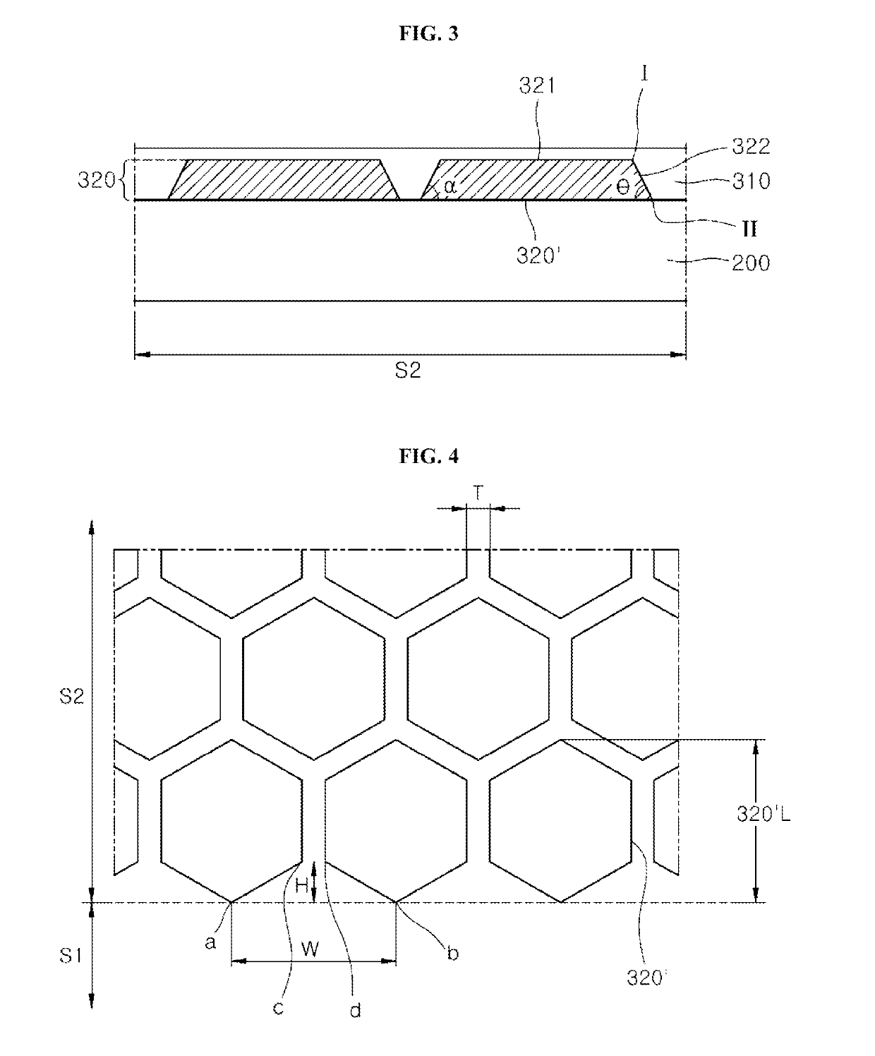
[0130]Printed patterns were formed along the periphery of an upper surface of a polyethylene terephthalate (PET) film through gravure coating of the composition for printed layers prepared in Preparative Example. The printed patterns had a bilayer structure of printed patterns including a first printed layer and a second printed layer sequentially formed on the PET film. A print roll for the first printed layer was formed with printed patterns having a regular hexagonal shape, each side of which had a length of 50 μm, and separated from each other. After printing the first printed pattern, a second printed pattern was formed thereon using another print roll for the second printed layer. A print roll for the second printed layer was formed with printed patterns having a rhombus shape, each side of which had a length of 50 μm, and separated from each other. A light shielding layer (thickness: 2.4 μm) was formed by heat-curing at 85° C. for 2 minutes. The shapes of the printed patterns...


PUM

PropertyMeasurementUnit
interior angleaaaaaaaaaa
base angleaaaaaaaaaa

Abstract

A polarizing plate and an optical display comprising the same. The polarizing plate includes a polarizer; and a bonding layer and a first polarizer protective film sequentially stacked on a lower surface of the polarizer, wherein the first polarizer protective film includes a light shielding layer formed in at least some region on an upper surface thereof and the light shielding layer is composed of at least one printed pattern, the printed pattern being composed of a single printed layer or multiple printed layers and having a first plane formed at a top portion thereof and an inclined angle θ of greater than about 0° to about 85° or less, the inclined angle being defined between the first polarizer protective film and an imaginary line I-II connecting one distal end point I of the first plane at the top portion of the printed pattern to a point II disposed on an outer peripheral surface of the printed pattern adjoining the first polarizer protective film and closest to the distal end point I.

Description

CROSS-REFERENCE TO RELATED APPLICATION[0001]This application claims priority to and the benefit of Korean Patent Application No. 10-2017-0177598, filed on Dec. 21, 2017 in the Korean Intellectual Property Office, the entire disclosures of which are incorporated herein by reference.BACKGROUND1. Field[0002]The present invention relates to a polarizing plate and an optical display including the same.2. Description of the Related Art[0003]An optical display is composed of a display region and a non-display region. The display region is light transmissive and displays an image to be viewed through a screen. The non-display region is disposed along the periphery of the display region to surround the display region. The non-display region is provided with a printed circuit board, a drive chip, and the like so as not to be visible to a user of an optical display. The non-display region may include a light shielding layer and the like.[0004]In recent years, a technique of coupling a polarize...

Claims


Application Information

Patent Timeline
Patent Type & Authority Applications(United States)
IPC IPC(8): G02B5/30
CPCG02B5/3025G02F1/133528G02B5/003G02F1/133512B32B7/12B32B2551/00B32B7/023C09D11/037C09D11/101C09J133/06C09J163/00G02B5/20
Inventor KIM, YOO JINKIM, JIN WOOSHIN, DONG YOONLEE, BAE WOOKCHO, SUNG MANHWANG, JI HYUN
Owner SAMSUNG SDI CO LTD
Learn More