Method and device for narrowband cellular communication
Active Publication Date: 2019-06-27
SHANGHAI LANGBO COMM TECH CO LTD
View PDF3 Cites 6 Cited by
Summary
Abstract
Description
Claims
Application Information
AI Technical Summary
This helps you quickly interpret patents by identifying the three key elements:
Problems solved by technology
Method used
Benefits of technology
Benefits of technology
The patent text describes a method for improving the efficiency of transmitting data over a wireless network using multiple radio signals. The method allows for the combined transmission of multiple transport blocks from a remote user equipment, reducing the need for separate signalings and improving spectrum utilization. Additionally, the method allows the user equipment to determine the time domain position of the radio signals without the need for two separate signalings, saving overhead in the process.
Problems solved by technology
However, the inventor finds through researches that the above intuitive method has very high requirements for the power consumption and the complexity of the smart terminal.
Therefore, this method is difficult to implement.
However, the inventor finds through researches that reusing the scheme of eD2D may increase the power consumption of the remote UE because the eD2D uses a Physical Sidelink Control Channel (PSCCH) period as a basic scheduling unit and does not support HARQ.
A Transport Block Size (TBS) of the signal transmitted by the first node may be small and incompatible with a TBS of a conventional Physical Uplink Shared Channel (PUSCH).
Method used
Image
Click on the blue label to locate the original text in one second.
Reading with bidirectional positioning of images and text.
Examples
embodiment 1
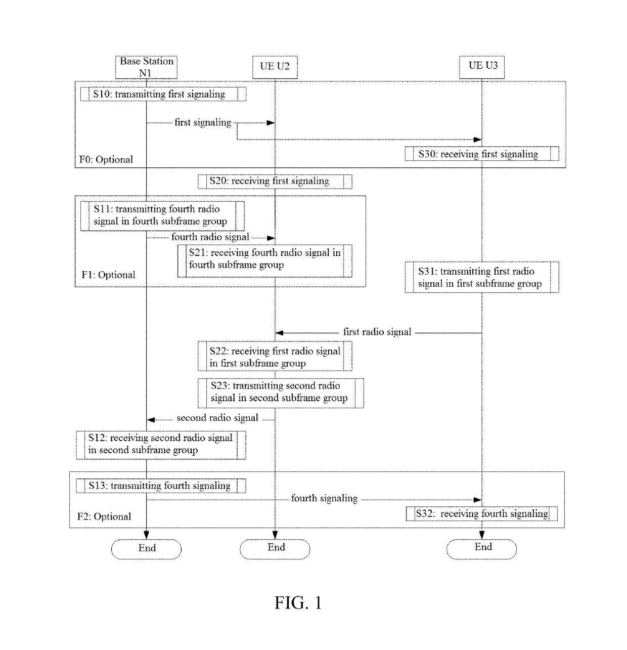
[0231]Embodiment 1 illustrates an example of a flowchart of relay transmission, as shown in FIG. 1. In FIG. 1, the base station N1 is a maintenance base station for a serving cell of the UE U2, the base station N1 is also a maintenance base station for a serving cell of the UE U3, and steps marked in boxes F0 to F2 are optional.
[0232]The base station N1 transmits a first signaling in S10, transmits a fourth radio signal in a fourth subframe group in S11, receives a second radio signal in a second subframe group in S12, and transmits a fourth signaling in S13.
[0233]The UE U2 receives the first signaling in S20, receives the fourth radio signal in the fourth subframe group in S21, receives a first radio signal in a first subframe group in S22, and transmits the second radio signal in the second subframe group in S23.
[0234]The UE U3 receives the first signaling in S30, transmits the first radio signal in the first subframe group in S31, and receives the fourth signaling in S32.
[0235]In...
embodiment 2
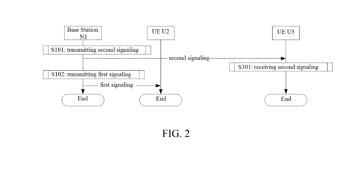
[0239]Embodiment 2 illustrates an example of a flowchart of the transmission of a second signaling, as shown in FIG. 2. In FIG. 2, the base station N1 is a maintenance base station for a serving cell of the UE U2, and the base station N1 is also a maintenance base station for a serving cell of the UE U3.
[0240]The base station N1 transmits a second signaling in S101, and transmits a first signaling in S102.
[0241]The UE U3 receives the second signaling in S301.
[0242]In Embodiment 2, the first signaling is used by the UE U2 to determine the first subframe group and the second subframe group. The second signaling is used by the UE U3 to determine the first subframe group and the second subframe group.
[0243]In one subembodiment, the first signaling and the second signaling are DCIs respectively.
[0244]In one subembodiment, the steps shown in FIG. 2 represent the steps marked by F0 shown in FIG. 1.
embodiment 3
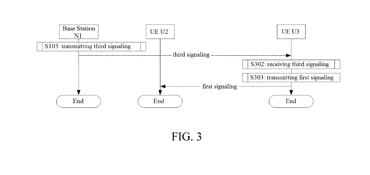
[0245]Embodiment 3 illustrates an example of a flowchart of the transmission of a third signaling, as shown in FIG. 3. In FIG. 3, the base station N1 is a maintenance base station for a serving cell of the UE U2, and the base station N1 is also a maintenance base station for a serving cell of the UE U3.
[0246]The base station N1 transmits a third signaling in S103.
[0247]The UE U3 receives the third signaling in S302, and transmits a first signaling in S303.
[0248]In Embodiment 3, the third signaling comprises scheduling information, and the first signaling comprises the scheduling information included in the third signaling; and the scheduling information comprises at least one among information relevant to the first subframe group, frequency domain resources occupied by the first radio signal in the first subframe group, a Modulation and Coding Scheme of the first radio signal, a Redundancy Version of the first radio signal, a HARQ process number for the first radio signal, and a New...
PUM
Abstract
The present disclosure provides a method and a device for narrowbandcellular communication. A User Equipment (UE) first receives a first signaling, then receives a first radio signal in a first subframe group, and then transmits a second radio signal in a second subframe group, wherein the first subframe group comprises one or more subframes, and the second subframe group comprises one or more subframes. The first signaling is used for determining the first subframe group, and the first signaling is used for determining the second subframe group. The first radio signal is used for determining the second radio signal. A transmitter of the first radio signal is a first node, a receiver of the second radio signal includes a second node, and the first node and the second node are non-co-located. The present disclosure improves transmission efficiency, shortens transmission delay, and has good compatibility with existing products.
Description
BACKGROUNDTechnical Field[0001]The present disclosure relates to transmission schemes in wireless communication systems, and in particular to a method and a device supporting wirelessrelay transmissions.Related Art[0002]The 3rd Generation Partner Project Release 9 (3GPP R9) has put forward a scheme of Layer-3 relaystation. The relaystation, for User Equipment (UE), has the functions of common base stations and is capable of scheduling data independently and transmitting a downlink HybridAutomatic Repeat reQuestAcknowledgement (HARQ-ACK).[0003]In conventional 3GPP systems, data transmission occurs between a base station and a UE. D2D was approved and discussed in the 3GPP R12. The essential characteristic of the D2D is to allow data transmission between UEs. Enhancements to LTE Device to Device (eD2D) were approved in the 3GPP R13. The main characteristic of the eD2D is to introduce a UE relay function. In the eD2D, a relay UE relays data exchange between a remote UE and a base ...
Claims
Application Information
Patent Timeline
Application Date:The date an application was filed.
Publication Date:The date a patent or application was officially published.
First Publication Date:The earliest publication date of a patent with the same application number.
Issue Date:Publication date of the patent grant document.
PCT Entry Date:The Entry date of PCT National Phase.
Estimated Expiry Date:The statutory expiry date of a patent right according to the Patent Law, and it is the longest term of protection that the patent right can achieve without the termination of the patent right due to other reasons(Term extension factor has been taken into account ).
Invalid Date:Actual expiry date is based on effective date or publication date of legal transaction data of invalid patent.

