Dynamic active and reactive power load sharing in an islanded microgrid

a micro-grid and active power technology, applied in the field of dynamic active and reactive power load sharing in an islanded micro-grid, can solve the problems of failure of inverter-based sources, less capacity available for reactive power contribution, and inapplicability

Inactive Publication Date: 2019-07-04
SWANSEA UNIV
View PDF0 Cites 20 Cited by
  • Summary
  • Abstract
  • Description
  • Claims
  • Application Information

AI Technical Summary

Problems solved by technology

Energy generation, storage, and management within a microgrid (MG) utilising renewable distributed generators (DGs) is a global issue as attention is continually drawn away from conventional sources of energy like fossil fuel.
Absence of such resources can result in the failure of the inverter-based sources [6]-[9].
This is due to the insensitivity of the droop scheme to the varying nature of the renewable resources [17].
The dynamic method in [17] was proposed for inductive MG, however, most MGs are located in the low-voltage side of the gird (i.e. distribution level) where network is mainly resistive, hence, the proposed scheme in [17] is not applicable.
Moreover, [17] did not consider the effect of the dynamic active power sharing on reactive power contribution of the units.
As a result, compared to other units, it has less capacity available for reactive power contribution.
As discussed below, this approach will also increase the reactive power demand from an AG (which in turn reduces the system efficiency).
However, the study did not take into account the generating capacity of the DG (i.e. the varying nature of renewable energy resources) in allocating the current sharing ratios among DGs.
Similar to droop control in inductive MG, these approaches are insensitive to available generation capacity of renewable resource.
As discussed above, the prior art schemes did not consider the varying nature of renewable resources in active and reactive power sharing in MGs.
This may lead to a shortage of supply which is compensated by the energy stored in the DC-links' capacitors (or a local energy storage) which causes a drop in the DC link voltage.
It is noted that since the other DGs are forced to reduce their generation, the energy demanded from the AG will not be optimized.
This is due to the insensitivity of a static virtual impedance control scheme to the input solar energy (see FIG. 12 and associated description below).

Method used


Image

  • Dynamic active and reactive power load sharing in an islanded microgrid
  • Dynamic active and reactive power load sharing in an islanded microgrid
  • Dynamic active and reactive power load sharing in an islanded microgrid

Examples


Embodiment Construction

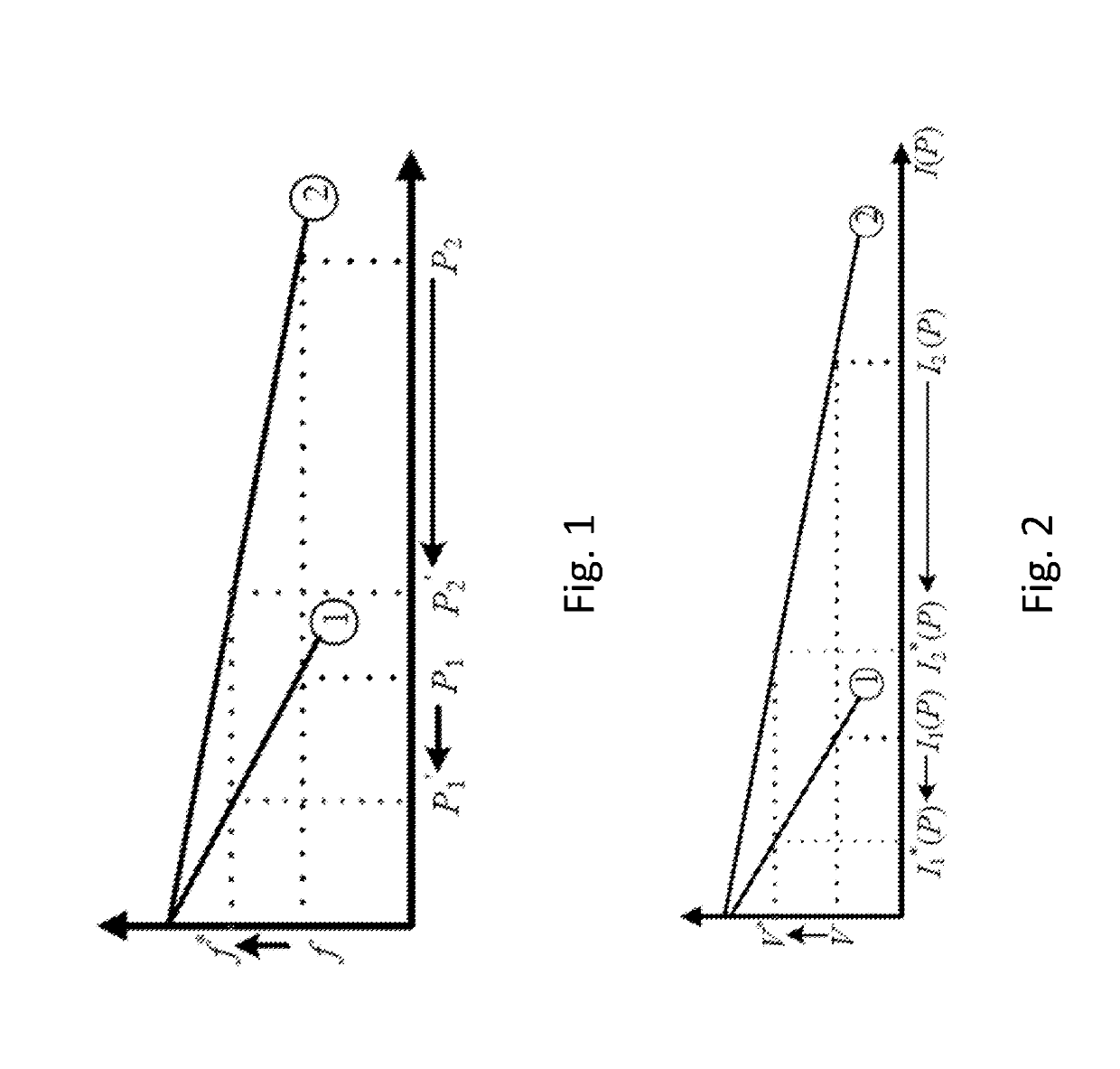
[0034]The aim of the present invention is to make active and reactive power sharing sensitive to solar irradiation (without the need for measuring it), such that in an MG having a plurality of DGs, when power generation of one unit drops (for example due to a reduction in solar irradiation):[0035]A. The other units do not drop their generation;[0036]B. The other units increase their generation, provided that enough irradiation is available; and,[0037]C. The units that generate less active power contribute more in reactive power, and vice versa.

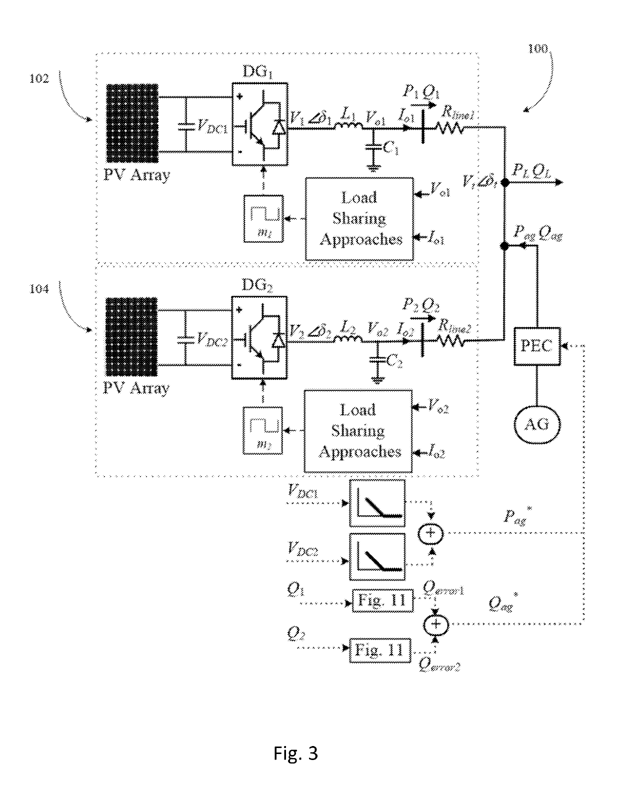
[0038]According to a first aspect of the present invention there is provided a method of managing a microgrid comprising the steps of:[0039]providing a microgrid comprising a plurality of renewable distributed generators, each renewable distributed generator having a respective inverter;[0040]determining a variable related to the available power from each of a plurality of renewable distributed generators;[0041]adjusting gains of each respecti...


PUM


Abstract

A method of managing a microgrid and control system is provided, in which the virtual resistance control gains (in αβ frame) of each respective inverter is dynamically adjusted based on a variable related to the available power from each of a plurality of renewable distributed generators.

Description

CROSS-REFERENCE TO RELATED APPLICATIONS[0001]This application claims priority to PCT Application No. PCT / GB2017 / 052403 filed Aug. 15, 2017, which claims the benefit of G.B. Application No. 1613956.0 filed Aug. 15, 2016, each of which is incorporated herein by reference in its entirety.FIELD[0002]The present invention is concerned with a method and system for managing an islanded micro grid comprising a plurality of distributed generators. In particular, the present invention is concerned with a method and system for controlling a microgrid comprising renewable distributed generators which is less reliant on the use of a fossil-fuelled auxiliary generator.BACKGROUND OF THE DISCLOSURE[0003]A reference list is provided at the end of the description. References in square brackets [ ] refer to that list, each of which is incorporated herein by reference in its entirety.[0004]Energy generation, storage, and management within a microgrid (MG) utilising renewable distributed generators (DGs...

Claims


Application Information

Patent Timeline
Patent Type & Authority Applications(United States)
IPC IPC(8): H02J3/46H02J3/38H02J3/18H02J3/16H02M7/48
CPCH02J3/46H02J3/383H02J3/18H02J3/16H02M7/48H02J2003/388Y02P80/14H02J2300/20H02J2300/24H02J3/381Y02E10/56H02J3/388
Inventor FAZELI, MEGHDADEGWEBE, AUGUSTINE
Owner SWANSEA UNIV
Why Eureka
Try Eureka