
Microphone array auto-directive adaptive wideband beamforming using orientation information from MEMS sensors

a microelectromechanical system and microphone array technology, applied in direction/deviation determination systems, frequency response correction, instruments, etc., can solve the problem of not being able to optimally capture audio in the interim, the gain of the beam pattern is no longer maximized in the direction of the source signal, and the repetition of the beam pattern is computationally intensive (and time-consuming). to achieve the effect of maximizing the gain of the beam pattern and minimizing the gain

Active Publication Date: 2019-07-04
STMICROELECTRONICS INT NV
View PDF0 Cites 15 Cited by
  • Summary
  • Abstract
  • Description
  • Claims
  • Application Information

AI Technical Summary

Benefits of technology

The patent text describes a technique called auto-directive beamforming which involves using a microphone array to determine the direction from which a signal is coming. This information is then used to steer a beam of microphones in the direction of the signal source. This helps to maximize the signal-to-noise ratio and minimize interference. The "technical effect" of this technique is improved signal quality in a noisy environment, allowing for better sound recording and directionality control.

Problems solved by technology

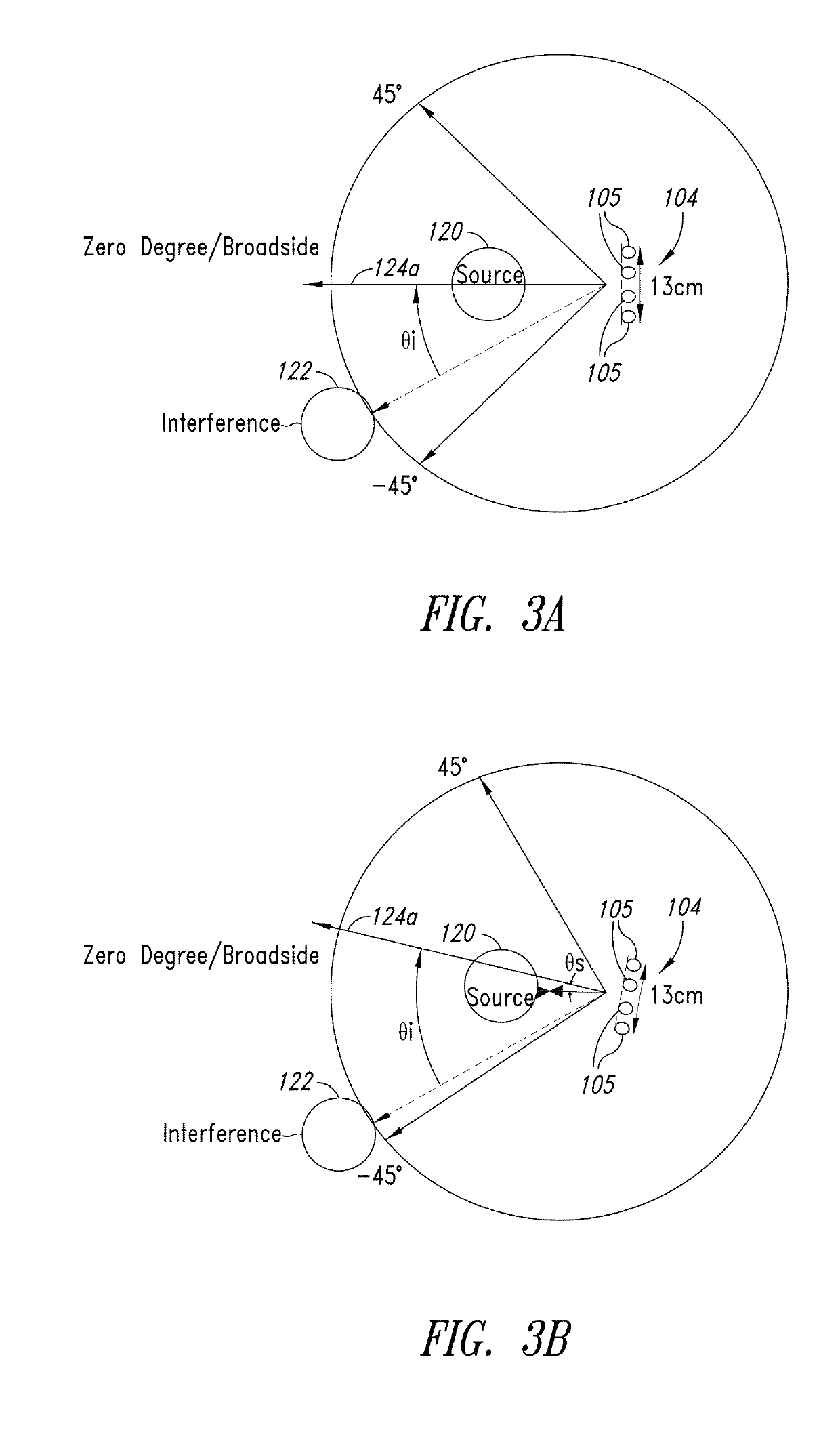
When a position of the microphone array changes while a position of the source signal and a position of the noise or interference remains the same, the gain of the beam pattern is no longer maximized in the direction of the source signal.
However, performing the beamforming again is computationally intensive (and time-consuming).
The beam pattern of the microphone array may not converge in time and some audio may not be optimally captured in the interim.

Method used


Image

  • Microphone array auto-directive adaptive wideband beamforming using orientation information from MEMS sensors
  • Microphone array auto-directive adaptive wideband beamforming using orientation information from MEMS sensors
  • Microphone array auto-directive adaptive wideband beamforming using orientation information from MEMS sensors

Examples


Embodiment Construction

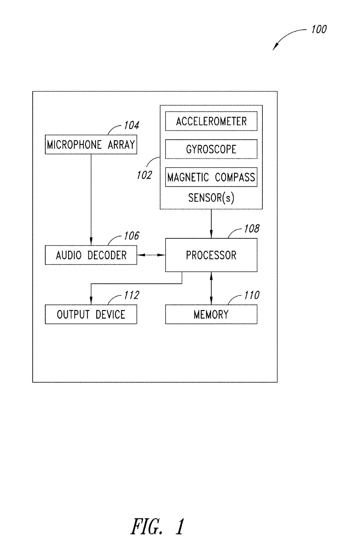
[0024]An array of microphones with adaptive wideband beamforming may be used to perform spatial filtering of a desired speech signal and suppress interfering noise (for example, that impinges on the array from other directions). In adaptive beamforming, knowledge of the direction of the desired source signal allows the signal to pass through unattenuated while optimally suppressing interfering noise from other spatial directions. The desired source signal may be at any angle or direction in relation to the microphone array and the position of the desired source signal may change over time. Source tracking as described herein may be used to identify one or more acoustic sources and find a direction of the desired speech source such that a beam can be formed in the direction of the source in an auto-directive manner.

[0025]The orientation of a device, such as a consumer electronic device, may change over time, for example in a continuous or intermittent manner. The device may be a hand...


PUM


Abstract

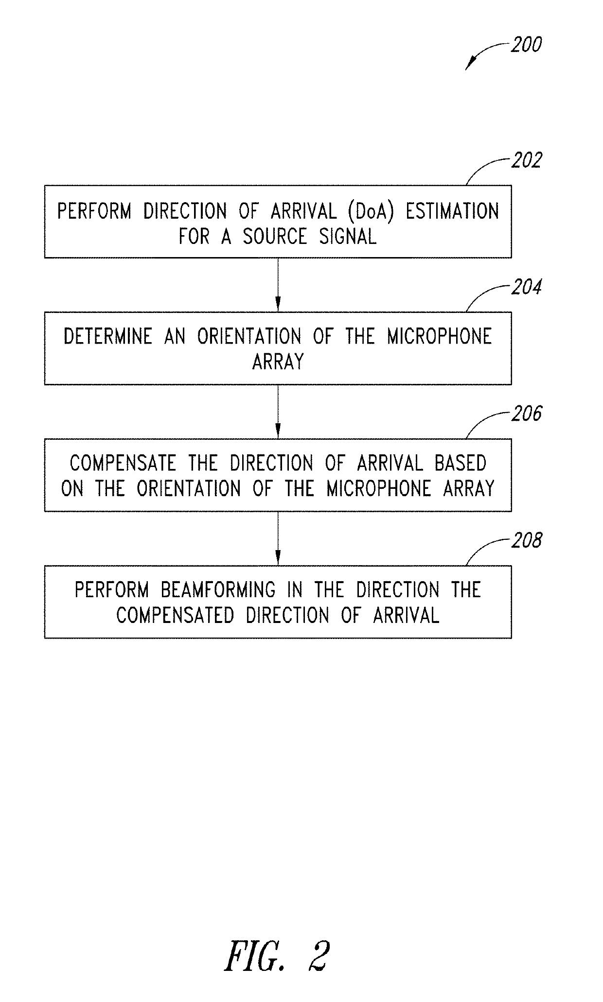
A method and apparatus for auto-directive adaptive beamforming for a microphone array using microelectromechanical systems (MEMS) sensor orientation information are provided. The microphone array captures audio and the MEMS sensor detects an orientation of the microphone array. A direction of arrival of a source signal is estimated based on the data representative of the audio. A change in an orientation of the microphone array is detected based on the orientation and the direction of arrival is compensates based on the change in the orientation of the microphone array. The apparatus pre-steers a beam of a beam pattern of the microphone array based on the compensated direction of arrival to retain the source signal in a broadside of the microphone array and performs adaptive wideband beamforming to null one or more interfering sources in the beam pattern while retaining the source signal in the broadside of the microphone array.

Description

BACKGROUNDTechnical Field[0001]The present disclosure is related to auto-directive adaptive beamforming for a microphone array using orientation information and, in particular, orientation information provided by a microelectromechanical systems (MEMS) sensor.Description of the Related Art[0002]Beamforming improves signal acquisition by directionally focusing a sensor array (or beam thereof) in a direction of a source signal and nulling angles at which sources of interference impinge on the array. Whereas traditional communication equipment and radar devices that use beamforming have a stationary array, modern devices, such as consumer electronic handheld devices, frequently change their position or orientation in relation to the source signal and interference. This renders beamforming sub-optimal. Re-converging the beam onto the source signal is both computationally intensive and time consuming.BRIEF SUMMARY[0003]In auto-directive beamforming, a microphone array determines a direct...

Claims


Application Information

Patent Timeline
IPC IPC(8): H04R3/00H04R1/40B81B7/00
CPCH04R3/005H04R1/406B81B7/00B81B2201/0235B81B2201/0242H04R2410/05G01S3/801G01S3/807G01S3/8083G10L21/0208G10L25/78G10L2021/02166H04R3/04G01S3/80
Inventor CHOWDHARY, MAHESHLOGARAMAN, PRASANTHKUMAR, ARUNBAHL, RAJENDAR
Owner STMICROELECTRONICS INT NV
Learn More