
Vehicle rack-and-pinion mechanism

Inactive Publication Date: 2019-07-11
HONDA MOTOR CO LTD
View PDF0 Cites 2 Cited by
  • Summary
  • Abstract
  • Description
  • Claims
  • Application Information

AI Technical Summary

Benefits of technology

The invention is about adding a coating film to a rack-and-pinion mechanism, which is made of a low specification material, to increase its strength without making it heavier. This results in a mechanism that can handle more surface pressure without increasing its size or weight. This invention is useful for providing heavy vehicles with rack-and-pinion mechanisms that can handle more weight without getting bigger or heavier.

Problems solved by technology

For this reason, when higher strength is required, the diameter of the rack itself needs to be larger to increase the contact area between the rack tooth and a pinion, but this causes a problem that a rack having a larger diameter is heavier.

Method used


Image

  • Vehicle rack-and-pinion mechanism
  • Vehicle rack-and-pinion mechanism
  • Vehicle rack-and-pinion mechanism

Examples


Embodiment Construction

[0023]An embodiment of the present invention will be described in detail with reference to the drawings as appropriate. Identical components are denoted by the same reference numerals, and duplicate descriptions thereof are omitted.

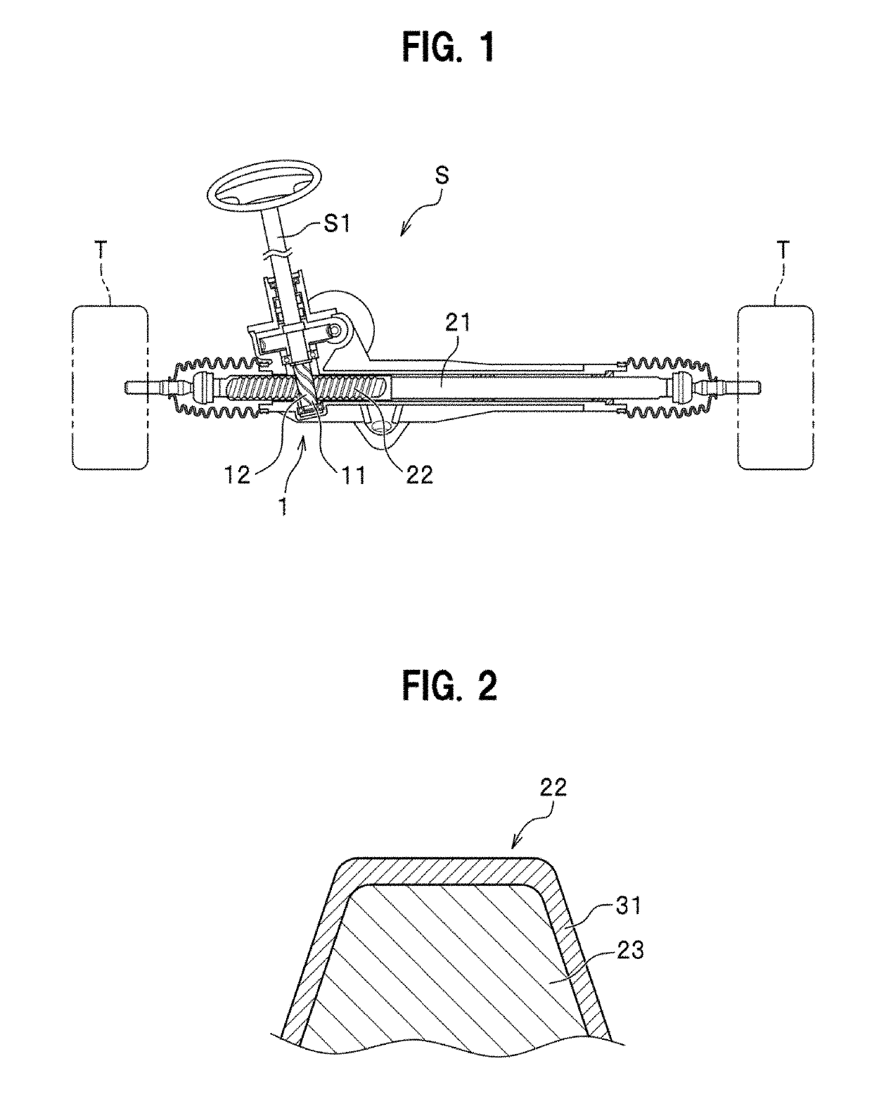
[0024]As shown in FIG. 1, a vehicle rack-and-pinion mechanism 1 of the present embodiment includes: a pinion 11 that is formed with a gear tooth 12 and rotatably supported about its axis; and a rack shaft 21 that is formed with a rack tooth 22 to be engaged with the gear tooth 12. In addition, the vehicle rack-and-pinion mechanism 1 of the present embodiment constitutes a steering device S of a vehicle. In other words, the pinion 11 constitutes a steering shaft S1 and is rotated about the axis in conjunction with the steering operation. Then, as the pinion 11 rotates, the engaging rack tooth 22 slides to change the steering angle of a tire T.

[0025]When the gear tooth 12 and the rack tooth 22 engage with each other in this steering device S, quietness is h...


PUM

PropertyMeasurementUnit
Hardnessaaaaaaaaaa

Abstract

A vehicle rack-and-pinion mechanism (1), which is applicable to a steering device (S), includes: a pinion (11) that is formed with a gear tooth (12) and is supported so as to be rotatable about its axis; and a rack shaft (21) that is formed with a rack tooth (22) to engage with the gear tooth (12), wherein the rack tooth (22) is formed, on its surface, with a coating film (31) of coatings having different degrees of hardness laminated.

Description

TECHNICAL FIELD[0001]The present invention relates to a vehicle rack-and-pinion mechanism used such as for a steering device of an automobile or the like.BACKGROUND OF THE INVENTION[0002]A rack constituting a steering device of an automobile or the like has been subjected to heat treatment such as hardening to increase rigidity, toughness, and strength. For example, Patent Document 1 proposes induction hardening for a rack tooth formed on a steering rack shaft. If the whole steering rack shaft is hardened, the steering rack shaft may be distorted and bend in an arc shape. However, induction hardening only for the rack tooth allows for enhancing strength of the rack tooth while preventing the steering shaft from bending.PRIOR ART DOCUMENTSPatent Documents[0003]Patent Document 1: Japanese Patent Application Publication No. H06-264147 ASUMMARY OF THE INVENTIONProblems to be Solved[0004]Incidentally, in the case of using a technique of increasing the strength of the rack tooth by heat t...

Claims


Application Information

Patent Timeline
IPC IPC(8): B62D3/12F16H55/26F16H55/06F16H19/04C23C14/06
CPCB62D3/126F16H55/26F16H55/06F16H19/04C23C14/0605C23C14/0641C23C14/0611C23C28/34C23C28/322C23C28/42C23C28/36C23C28/343F16H57/041C23C14/06
Inventor SATO, MASATO
Owner HONDA MOTOR CO LTD
Features
  • Generate Ideas
  • Intellectual Property
  • Life Sciences
  • Materials
  • Tech Scout
  • Unparalleled Data Quality
  • Higher Quality Content
  • 60% Fewer Hallucinations
Learn More