Contaminated soil purification method

a technology of contaminated soil and purification method, which is applied in the direction of fluid removal, inference method, borehole/well accessories, etc., can solve the problem of taking effort to perform, and achieve the effect of less manpower and prediction accuracy of the management function to be raised

Active Publication Date: 2019-08-01
TAKENAKA KOMUTEN CO LTD
View PDF5 Cites 1 Cited by
  • Summary
  • Abstract
  • Description
  • Claims
  • Application Information

AI Technical Summary

Benefits of technology

[0013]In the contaminated soil purification method of the third aspect of the present disclosure, the injection concentration or the injection temperature of the injection liquid is changed, the management function is also corrected based on the injection concentration or the injection temperature after the change, and the initial concentration or the initial temperature in the management function are replaced with the concentration or the temperature of the groundwater after the predetermined time has elapsed. The difference between the predicted concentration and the actual measured concentration calculated by the management function or the difference between the predicted temperature calculated by the management function and the actual measured temperature is thereby reduced, enabling the prediction accuracy of the management function to be raised.
[0014]Raising the prediction accuracy of the management function enables an injection liquid having an appropriate amount of the purification agent or the activator added thereto, or an injection liquid having an appropriate temperature, to be injected into the contaminated soil. The purification agent or the activator in the contaminated soil can thereby be suppressed from becoming excessive or insufficient.
[0015]The contaminated soil purification method according to the present disclosure enables an operation to purify contaminated soil to be performed with less manpower.

Problems solved by technology

In the purification unit disclosed in JP-A No. 2005-52733, checking of the recovered liquid and regulation of the addition amount of oil decomposition accelerator for injection into the contaminated soil needs to be performed by a manual operation on each occasion and so takes effort to perform.

Method used


Image

  • Contaminated soil purification method
  • Contaminated soil purification method
  • Contaminated soil purification method

Examples


first exemplary embodiment

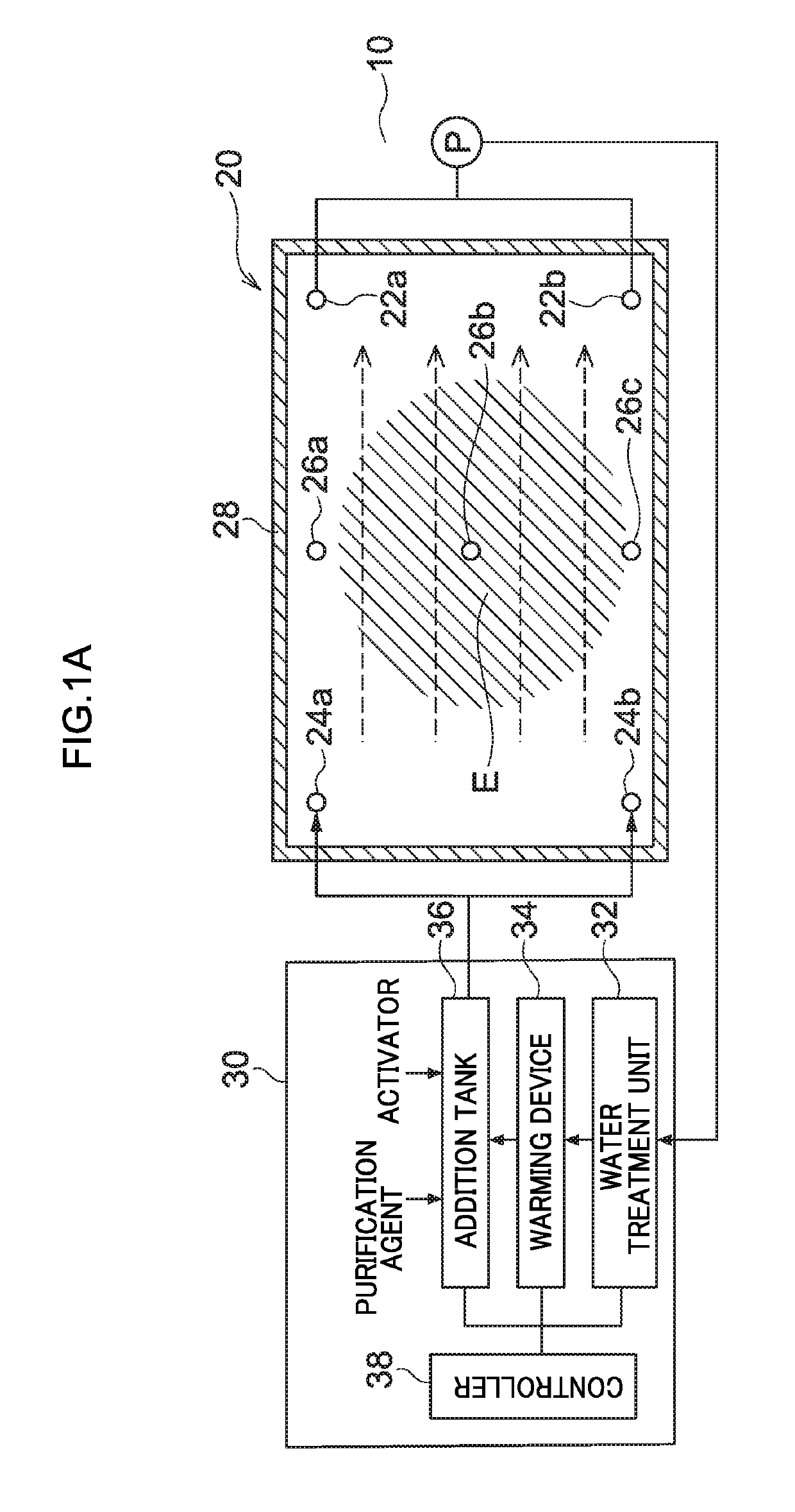
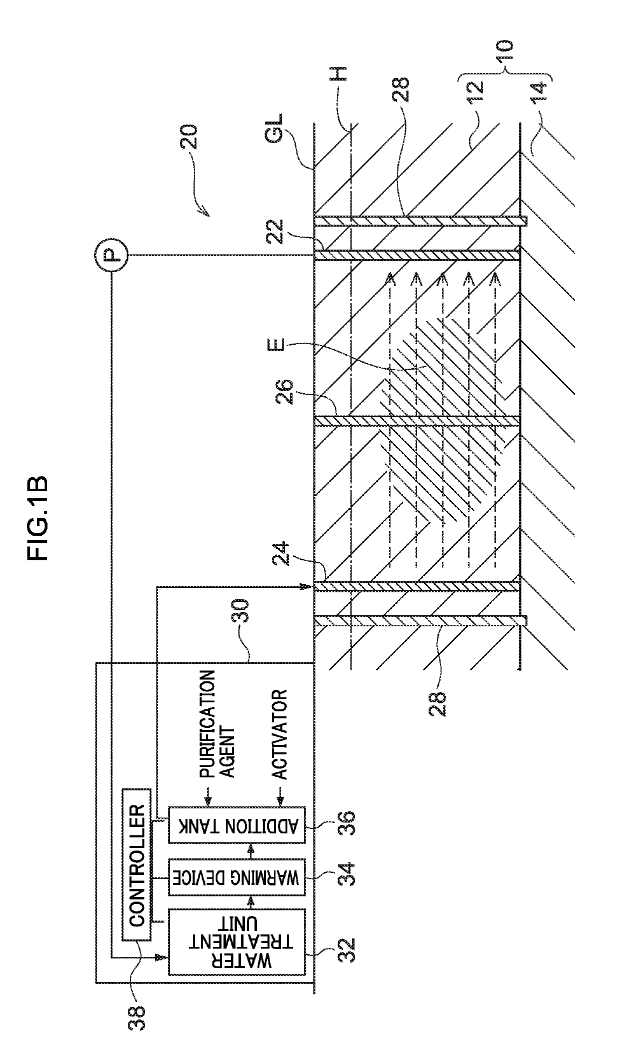
[0028]Overall Configuration A contaminated soil purification system 20 of a first exemplary embodiment illustrated in FIG. 1A and FIG. 1B is a contaminated soil purification system used to decompose contaminants contained in subsurface soil 10. The contaminated soil purification system 20 includes water pumping wells 22, water injection wells 24, observation wells 26, and a water-shielding wall28, each constructed in the subsurface soil 10, and a purification unit 30 that is constructed above ground level GL and that circulates groundwater between the subsurface soil 10, the water pumping wells 22, and the water injection wells 24.

[0029]Contaminated Soil

[0030]The subsurface soil 10 is soil below the ground level GL, and includes an aquifer layer 12 through which groundwater flows, and an impermeable layer 14 through which groundwater does not flow. A portion of the subsurface soil 10 in which contaminants are present at a reference value or greater (for example a value set for each ...

second exemplary embodiment

[0076]A contaminated soil purification system according to a second exemplary embodiment employs the configuration and purification method of the contaminated soil purification system 20 according to the first exemplary embodiment, and additionally employs a management function, described below, to predict a time at which the concentration of the purification agent or activator in the groundwater in the subsurface soil 10 will reach the target concentration.

[0077]Management Function

[0078]In FIG. 3, a management function f (t), representing a relationship between elapsed time t from the start of injection of the injection liquid into the subsurface soil 10 and a predicted concentration C of the groundwater in the observation wells 26, is illustrated by a solid line. For example, the predicted concentration at a time t1 is a predicted concentration C1.

[0079]The management function f (t) is represented by the following Equation.

f(t)=(A−D) / [1+(B / t)G]+D  Equation 1

[0080]A: concentration ...

third exemplary embodiment

[0102]A contaminated soil purification system according to a third exemplary embodiment predicts the time at which the concentration of the purification agent or activator in the groundwater will reach a target concentration using a management function similarly to in the contaminated soil purification system according to the second exemplary embodiment, and additionally corrects the management function by comparing the predicted concentration calculated using the management function against an actual measured concentration.

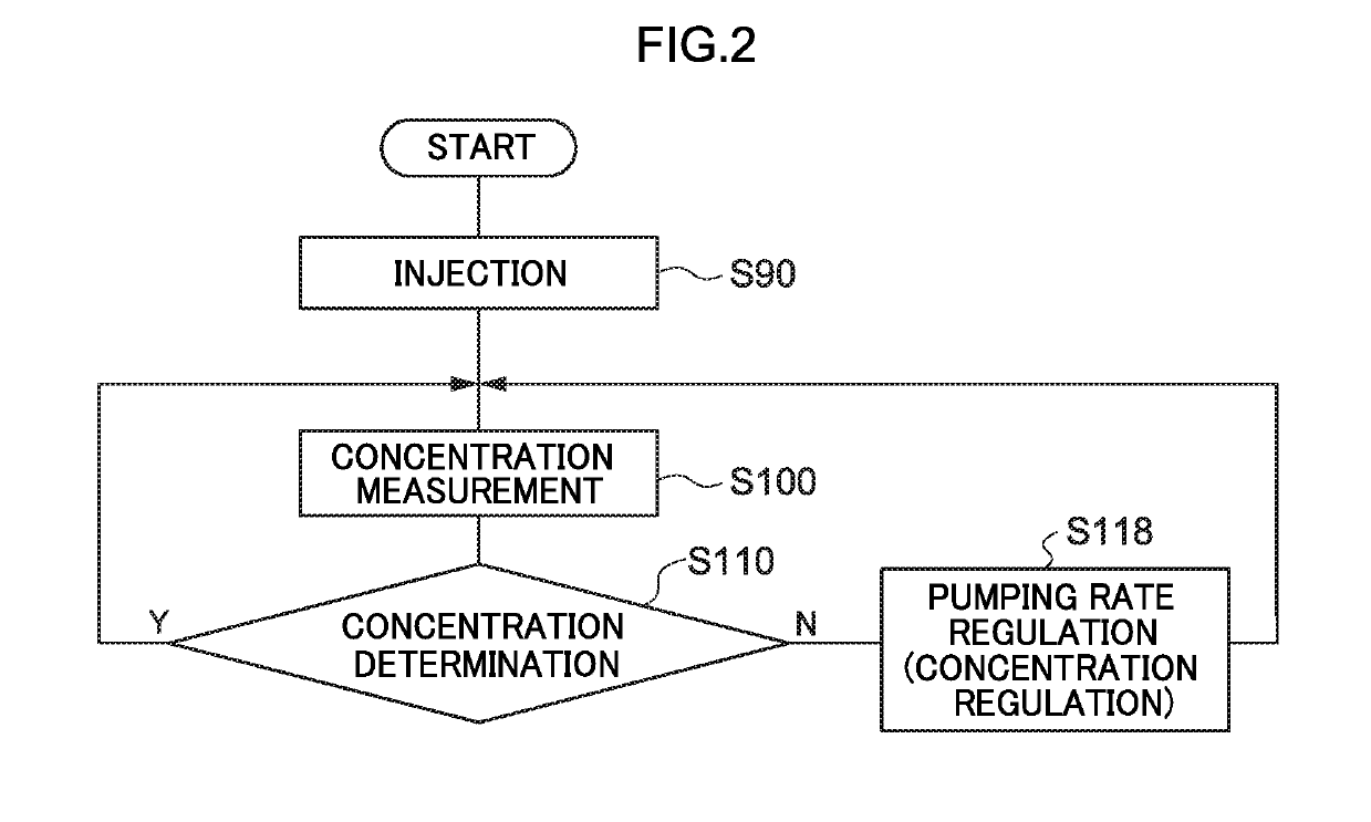
[0103]Explanation follows regarding the purification method of the contaminated soil E used by the contaminated soil purification system according to the third exemplary embodiment, with reference to the flowchart illustrated in FIG. 4 and the graph illustrated in FIG. 5. Explanation regarding elements similar to those of the first exemplary embodiment and the second exemplary embodiment is omitted as appropriate.

[0104]In the purification method of the third exem...


PUM


Abstract

A contaminated soil purification system for decomposing a contaminant in contaminated soil E. The contaminated soil purification system includes: injecting, into contaminated soil through a water injection well, an injection liquid containing a purification agent to decompose a contaminant or an activator to stimulate biological decomposition by the purification agent; a process of measuring a concentration of the purification agent or the activator in groundwater in an observation well or in a pumping well, the observation well or the pumping well being provided at a location spaced apart from the water injection well; and a process of, based on the concentration that has been measured, automatically controlling an addition amount of the purification agent or the activator to the injection liquid or automatically controlling a pumping amount of water from the pumping well.

Description

CROSS REFERENCE TO RELATED APPLICATIONS[0001]This application is a National Stage Application, filed under 35 U.S.C. § 371, of International Application No. PCT / JP2017 / 031017, filed Aug. 29, 2017, which claims priority to Japanese Application No. 2016-170144, filed Aug. 31, 2016; the contents of which are hereby incorporated by reference in their entirety.BACKGROUNDTechnical Field[0002]The present disclosure relates to a contaminated soil purification method.Description of Related Art[0003]Japanese Patent Application Laid-Open (JP-A) No. 2005-52733 discloses a purification unit in which a liquid to which an oil decomposition accelerator has been added is injected into oil-contaminated soil. The injected liquid permeates the contaminated soil and is pumped up from a water-collection well. The turbidity of the recovered liquid that has been pumped up is checked by a turbidity meter or by visual inspection by an operator, and the addition amount of the oil decomposition accelerator for...

Claims


Application Information

Patent Timeline
Patent Type & Authority Applications(United States)
IPC IPC(8): B09C1/08B09C1/10E21B43/12G06N5/04
CPCB09C1/08B09C1/10E21B43/121G06N5/04B09C1/02B09C2101/00
Inventor NAKASHIMA, TOMOHIROSHIMIZU, TAKAAKIKIYOTOMO, HARUKASHIMIZU, YAMATOOKUDA, NOBUYASUFURUKAWA, YASUHIDEYAMAZAKI, YUJIMUKAI, KAZUHIROINABA, KAORU
Owner TAKENAKA KOMUTEN CO LTD
Why Eureka
Try Eureka