
Managing automated driving complexity of the forward path using perception system measures

a technology of perception system and advanced path, applied in the direction of process and machine control, digital computer details, instruments, etc., can solve the problems of limited, geo-fenced, level 4 of automated driving system

Active Publication Date: 2019-08-01
GM GLOBAL TECH OPERATIONS LLC
View PDF5 Cites 28 Cited by
  • Summary
  • Abstract
  • Description
  • Claims
  • Application Information

AI Technical Summary

Benefits of technology

The patent describes an automated driving system for vehicles that uses a computing system to determine the best way to drive in different regions along a route. The system uses sensor data to calculate a complexity metric for each region, which indicates the level of difficulty in determining the best trajectory for the vehicle. If the complexity metric is low, the system automatically determines the trajectory for the vehicle to travel in the region. If the complexity metric is high, the system alerts the driver and allows them to take control of the vehicle. The system can also adjust the computing system to allocate computational resources and perform a minimal risk condition maneuver if the trajectory cannot be determined. The technical effect of this system is to improve the automated driving experience of the vehicle by making the driving system more efficient and effective in identifying the best path through complex regions.

Problems solved by technology

Level 4 automated driving systems are currently limited to small, geo-fenced areas and low speed operation due to the potential computational complexity involved when the vehicle encounters certain situations.
Further yet, it includes performing a minimal risk condition maneuver of the vehicle if the trajectory cannot be determined by the computing system.

Method used


Image

  • Managing automated driving complexity of the forward path using perception system measures
  • Managing automated driving complexity of the forward path using perception system measures
  • Managing automated driving complexity of the forward path using perception system measures

Examples


Embodiment Construction

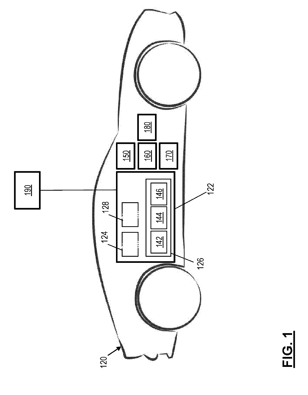
[0025]The following description is merely exemplary in nature and is not intended to limit the present disclosure, its application or uses. It should be understood that throughout the drawings, corresponding reference numerals indicate like or corresponding parts and features. As used herein, the term module refers to processing circuitry that may include an application specific integrated circuit (ASIC), an electronic circuit, a processor (shared, dedicated, or group) and memory that executes one or more software or firmware programs, a combinational logic circuit, and / or other suitable components that provide the described functionality.

[0026]Generally, automated or autonomous vehicles include least some aspects of a safety-critical control function, e.g., steering, throttle, or braking, occur without direct driver input. In one or more examples, vehicles that provide safety warnings to drivers but do not perform a control function are, in this context, not considered automated, e...


PUM


Abstract

Technical solutions are described for controlling an automated driving system of a vehicle. An example method includes computing a complexity metric of an upcoming region along a route that the vehicle is traveling along. The method further includes, in response to the complexity metric being below a predetermined low-complexity threshold, determining a trajectory for the vehicle to travel in the upcoming region using a computing system of the vehicle. Further, the method includes in response to the complexity metric being above a predetermined high-complexity threshold, instructing an external computing system to determine the trajectory for the vehicle to travel in the upcoming region. If the trajectory cannot be determined by the external computing system a minimal risk condition maneuver of the vehicle is performed.

Description

INTRODUCTION[0001]The subject disclosure generally relates to an automated driving system for a vehicle, and particularly to using perception system complexity information to support conditional and high automation levels.[0002]Autonomous vehicles can operate in various operational modes. For example, in a “fully-automated” operational mode (sometimes referred to as Level 5 automation by National Highway Transportation Safety Agency (NHTSA)) a computing system is used to navigate and / or maneuver the vehicle along a travel route with no input from a human driver. In a “semi-automated” operational mode (Level 3 automation per NHTSA), the vehicle can perform full self-driving functions, but may need human intervention in various situations or may request the driver to take control (with some amount of delay allowed in the response). There are various other operational modes that facilitate functions like anti-lock brakes, electronic stability control, lane-keeping and the like. Further...

Claims


Application Information

Patent Timeline
Patent Type & Authority Applications(United States)
IPC IPC(8): B60W30/09B60W30/095B60W30/12G05D1/02G06F15/18G06V10/764
CPCG06N20/00B60W30/09B60W30/12G05D1/0221B60W30/0956B60W50/00B60W50/0097B60W2050/0075G06N3/08B60W60/0015B60W60/0018B60W2050/065B60W50/06B60W60/0053B60W60/0059B60W50/14B60W2050/143B60W2556/10G06V20/56G06V10/82G06V10/803G06V10/764G06N3/044G06F18/251
Inventor GRIMM, DONALD K.TONG, WEIZENG, SHUQINGMUDALIGE, UPALI P.
Owner GM GLOBAL TECH OPERATIONS LLC
Learn More