Multilayer lc filter

a multi-layer lc filter and filter technology, applied in the direction of fixed inductances, basic electric elements, inductances, etc., can solve the problems of reducing the inductance values of the second inductor and the third inductor, and achieve the effect of small loss of insertion of the multi-layer lc filter

Active Publication Date: 2019-08-08
MURATA MFG CO LTD
View PDF3 Cites 2 Cited by
  • Summary
  • Abstract
  • Description
  • Claims
  • Application Information

AI Technical Summary

Benefits of technology

[0030]It is preferable that, when the multilayer body is seen in the lamination direction of the dielectric layers, an air-core portion of the first inductor and an air-core portion of the second inductor at least partially overlap each other; a section where the air-core portion of the first inductor and the air-core portion of the second inductor overlap each other overlap neither the capacitor conductor pattern nor the ground conductor pattern, or overlap the capacitor conductor pattern or the ground conductor pattern partially but not completely; an air-core portion of the third inductor and an air-core portion of the fourth inductor at least partially overlap each other; and a section where the air-core portion of the third inductor and the air-core portion of the fourth inductor overlap each other overlap neither the capacitor conductor pattern nor the ground conductor pattern, or overlap the capacitor conductor pattern or the ground conductor pattern partially but not completely. In this case, magnetic flux generation of each of the first inductor to the fourth inductor is not reduce or prevented by the capacitor conductor pattern

Problems solved by technology

In a case in which the first inductor and the first capacitor of the first LC parallel resonator are connected by a via conductor additionally provided in the second thickness region, and not by the first input/output terminal and the ground terminal, and the fourth inductor and the fourth capacitor of the fourth LC parallel resonator are connected by a via conductor additionally provided in the second thi

Method used


Image

  • Multilayer lc filter
  • Multilayer lc filter
  • Multilayer lc filter

Examples


first preferred embodiment

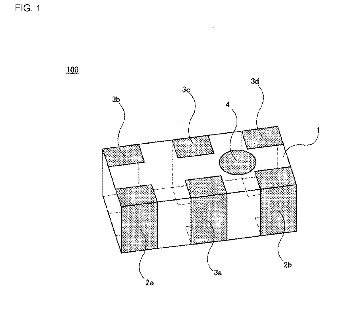
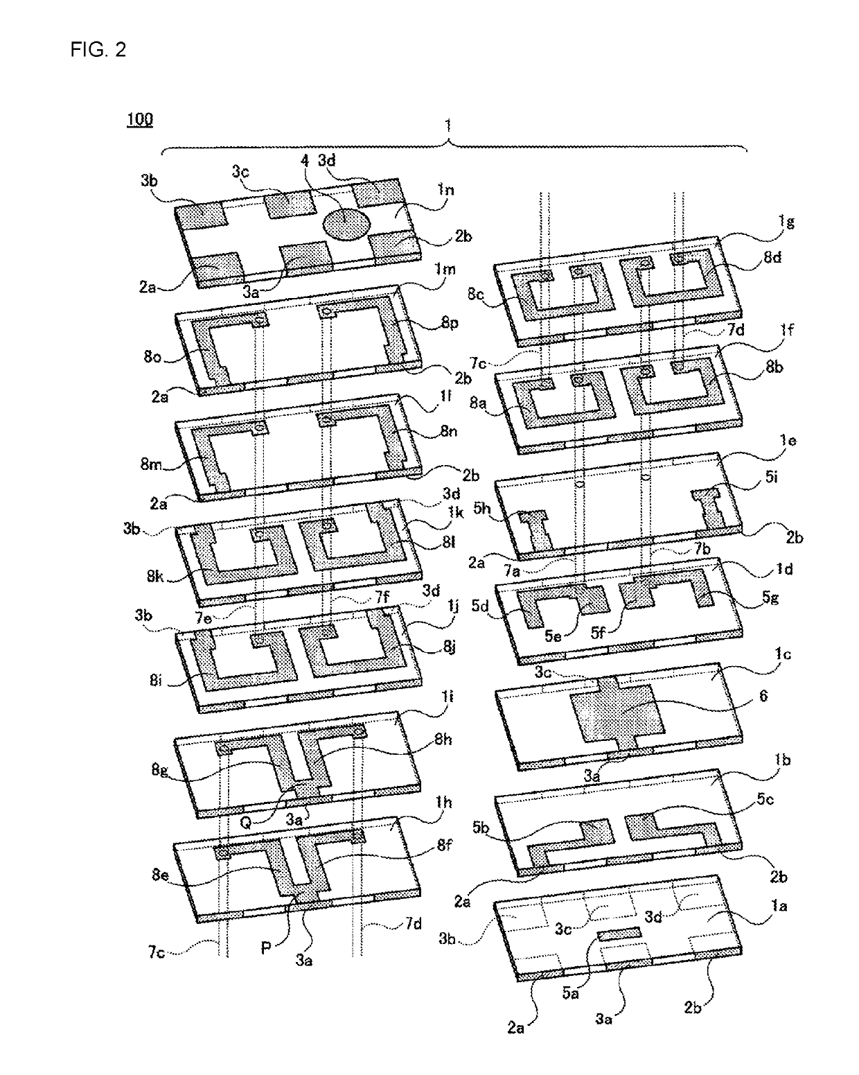
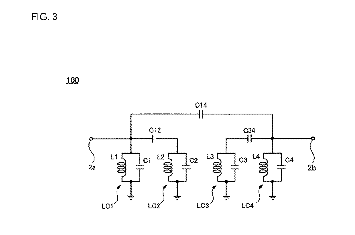
[0043]A multilayer LC filter 100 according to a first preferred embodiment of the present invention is illustrated in FIGS. 1 to 3. Note that FIG. 1 is a perspective view of the multilayer LC filter 100. FIG. 2 is an exploded perspective view of the multilayer LC filter 100. FIG. 3 is an equivalent circuit diagram of the multilayer LC filter 100.

[0044]The multilayer LC filter 100 includes a multilayer body 1. On an outer surface of the multilayer body 1, a first input / output terminal 2a, a second input / output terminal 2b, and four ground terminals 3a, 3b, 3c and 3d are preferably provided. More specifically, the first input / output terminal 2a, the ground terminal 3a, and the second input / output terminal 2b are provided on a side surface of the multilayer body 1 on the front side in FIG. 1. The ground terminal 3b, the ground terminal 3c, and the ground terminal 3d are provided on a side surface of the multilayer body 1 on the rear side in FIG. 1.

[0045]Each of the first input / output t...

second preferred embodiment

[0099]A multilayer LC filter 200 according to a second preferred embodiment of the present invention is illustrated in FIGS. 7A and 7B. Note that FIG. 7A is a see-through plan view of the multilayer LC filter 200, and FIG. 7B is a see-through side view of the multilayer LC filter 200.

[0100]The multilayer LC filter 200 is preferably obtained by modifying the multilayer LC filter 100 according to the first preferred embodiment. Specifically, in the multilayer LC filter 100, the third inductor L3 is provided in the second thickness region TD2, and the fourth inductor L4 is provided in the first thickness region TD1. Conversely, in the multilayer LC filter 200, the third inductor L3 is provided in the first thickness region TD1, and the fourth inductor L4 is provided in the second thickness region TD2, as illustrated in FIG. 7B. In response to this modification, in the multilayer LC filter 200, shapes, positions, and other configurations of some of the capacitor conductor patterns 5a to...

third preferred embodiment

[0103]A multilayer LC filter 300 according to a third preferred embodiment of the present invention is illustrated in FIGS. 8A and 8B. Note that FIG. 8A is a see-through plan view of the multilayer LC filter 300, and FIG. 8B is a see-through side view of the multilayer LC filter 300.

[0104]The multilayer LC filter 300 is also obtained by modifying the multilayer LC filter 100 according to the first preferred embodiment. Specifically, in the multilayer LC filter 100, the first thickness region TD1 is preferably provided on the side closer to one main surface (the upper-side main surface in the drawing) of the multilayer body 1, and the second thickness region TD2 is preferably provided on the interior side of the multilayer body 1; conversely, in the multilayer LC filter 300, the second thickness region TD2 is preferably provided on the side closer to one main surface (the upper-side main surface in the drawing) of the multilayer body 1, and the first thickness region TD1 is preferabl...


PUM


Abstract

A multilayer body includes a first inductor and a second inductor provided in a first planar region, and a third inductor and a fourth inductor provided in a second planar region when viewed in a lamination direction of dielectric layers of the multilayer body. When the multilayer body is viewed in a direction perpendicular or substantially perpendicular to the lamination direction of the dielectric layers, the first inductor L1 and the fourth inductor are provided in a first thickness region, and the second inductor and the third inductor are provided in a second thickness region

Description

CROSS REFERENCE TO RELATED APPLICATIONS[0001]This application claims the benefit of priority to Japanese Patent Application No. 2016-217259 filed on Nov. 7, 2016 and is a Continuation Application of PCT Application No. PCT / JP2017 / 036191 filed on Oct. 4, 2017. The entire contents of each application are hereby incorporated herein by reference.BACKGROUND OF THE INVENTION1. Field of the Invention[0002]The present invention relates to a multilayer LC filter in which four LC parallel resonators are provided inside a multilayer body in which a plurality of dielectric layers are laminated, and more particularly, to a multilayer LC filter that has desired frequency characteristics obtained by necessary magnetic coupling between inductors defining the LC parallel resonators being appropriately performed, and has a reduced height.2. Description of the Related Art[0003]A multilayer LC filter in which an LC parallel resonator defined by an inductor and a capacitor is formed inside a multilayer ...

Claims


Application Information

Patent Timeline
IPC IPC(8): H03H7/09H01F27/00H03H7/01H01F17/00
CPCH03H7/09H01F27/00H03H7/1741H01F17/0013H03H2001/0085H01F2017/0026H01F27/292H03H7/1775H03H7/1708H03H7/0115
Inventor MASUDA, HIROSHI
Owner MURATA MFG CO LTD
Why Eureka
Try Eureka