
Ultra-low frequency tuned liquid mass damper and design method of the same

a damper and liquid mass technology, applied in the field of ultra-low frequency tuned liquid mass dampers and design methods of the same, can solve the problems of insufficient spring stiffness, shortening the life of the bridge, and affecting the comfort of vehicles and pedestrians, so as to improve the price-performance of vibration damping devices, reduce the static elongation of springs, and increase the stiffness of springs

Active Publication Date: 2019-08-15
CHINA RAILWAY BRIDGE SCI RES INST LTD +1
View PDF5 Cites 13 Cited by
  • Summary
  • Abstract
  • Description
  • Claims
  • Application Information

AI Technical Summary

Benefits of technology

The present invention provides an ultra-low frequency tuned liquid mass damper that can maintain the frequency of structural vibration below 0.5 Hz while significantly reducing the spring static elongation, damper spring consumption, and installation space. The buoyancy effect of the liquid helps keep the damper stable during movements, avoiding tilting and lateral oscillation. The damping parameters can be easily adjusted by changing the shape of the mass block and the flap, and the clearance between the mass block and the damping box. This results in improved price-performance of vibration damping devices, meeting the limitations on installation space for dampers under actual construction circumstances.

Problems solved by technology

Bridge structures tend to vibrate under loads from the outside wind and vehicles, resulting in discomfort vehicles and pedestrians, accumulating fatigue damages to and shorter lifetime of the bridge even collapses of the bridge structures.
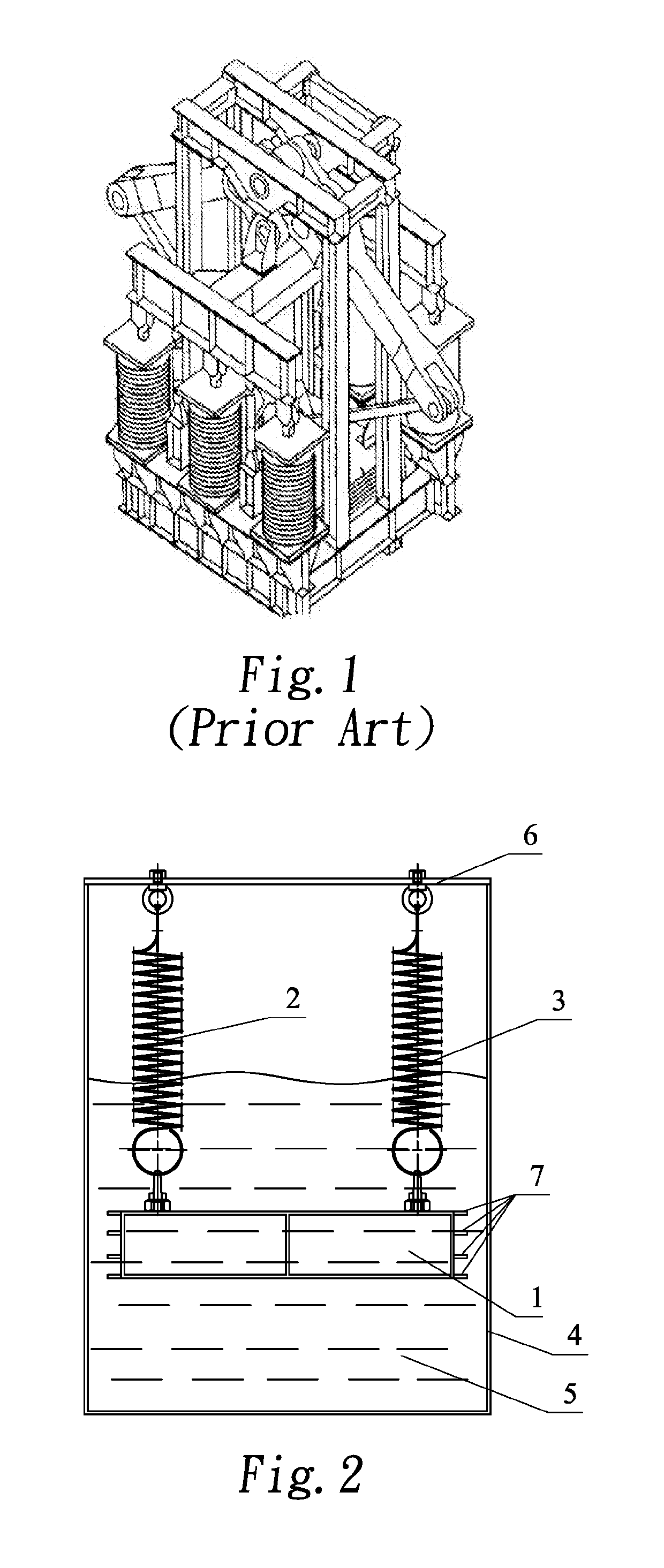
The main challenges for the conventional TMD to achieve ULF are insufficient stiffness of springs, along with the dead weight of the mass block which is hard to balance.
1. The spring consumption can barely be reduced, while the damper needs a complicated lever-based transmission system with a sophisticated structure, which is highly demanding for manufacturing accuracy and field assembly. And the materials without damping effects, such as bearings, brackets, levers and hinge joints, substantially increase the cost for vibration reduction.
2. It's hard to make the frequency even lower, and considering the damper needs a complicated lever-based transmission system, more rotary hinges brings more rotational frictions from the bearings, which gives a greater initial damping to the damper and makes it insensitive to small amplitudes. And in this case, it is also hard to optimize the parameters of the damper. In conclusion, it is very difficult for such solution to be promoted and applied to structural vibration control with requirements on lower frequency.

Method used


Image

  • Ultra-low frequency tuned liquid mass damper and design method of the same
  • Ultra-low frequency tuned liquid mass damper and design method of the same
  • Ultra-low frequency tuned liquid mass damper and design method of the same

Examples


example 1

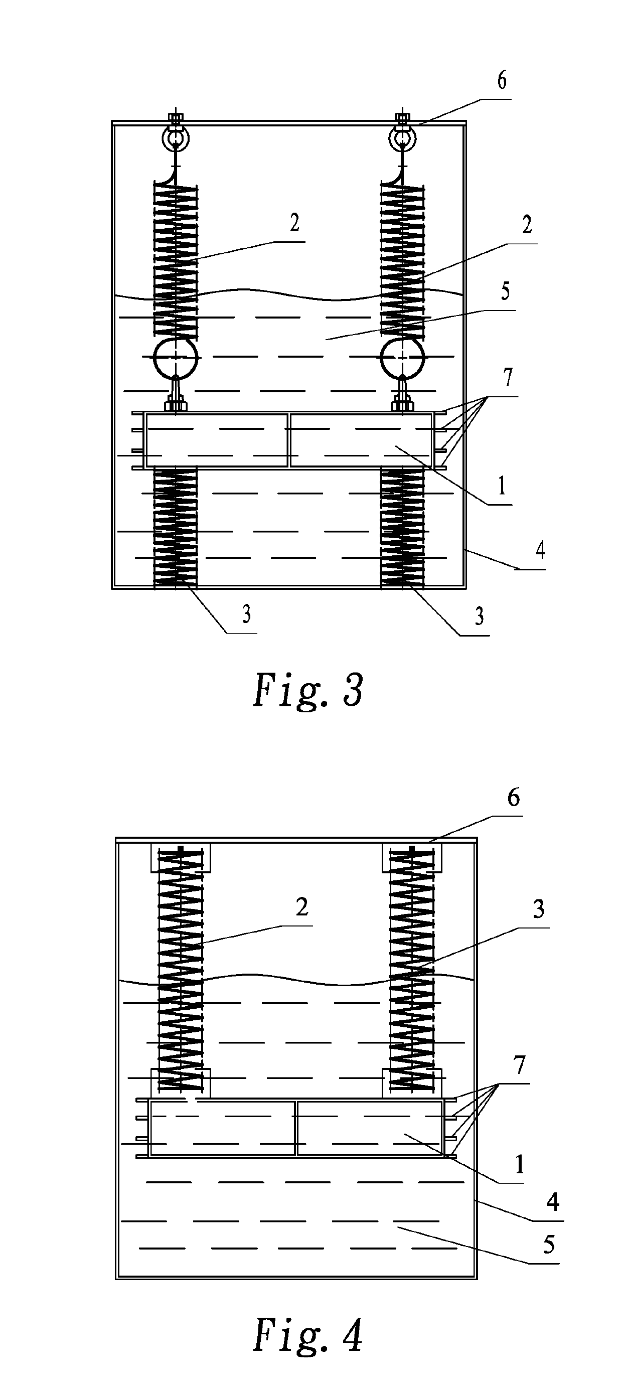
[0044]As shown in FIG. 2, this example for the present invention provides a ULF tuned liquid mass damper, comprising a damping box which is provided with a spring set secured at one end to the damping box, the other end connected with a mass block; the damping box is filled with damping fluid, and the mass block is completely immersed or partially immersed in the damping liquid.

[0045]The upper portion of the damping box is fixed with a connecting plate; the spring set is secured to the connecting plate. This connection method can connect the damper box and the spring set as a whole, better transmit vibrations when they occur, and support a more sufficient damping effect from the damping liquid and the spring set, thereby improving the damping effect of the damper.

[0046]It is also available to set flaps on laterals of the block mass with each flap set disposed on the same level perpendicular to the axis of the spring set. With these flaps, the effective damping area between the dampi...

example 2

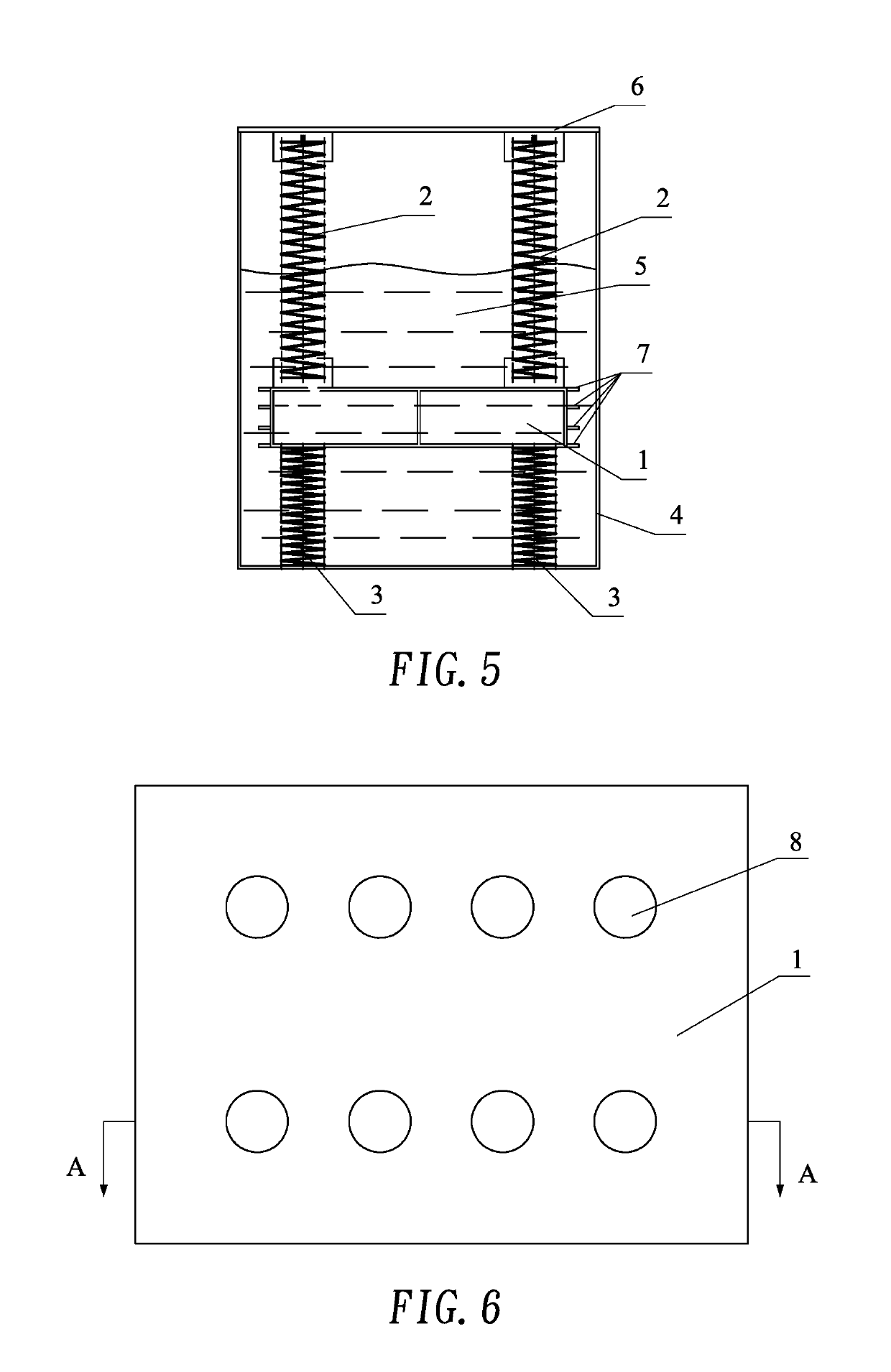
[0048]As shown in FIG. 3, the difference between this example and Example 1 is that the spring set in this example comprises a first spring group located above the mass block and a second spring group opposite to the first and located below the mass block. The second spring group has one end connected to the bottom plate of the damping box. And the first spring group consists of two cylindrical spiral springs while the second spring group consists of two cylindrical spiral compression springs.

example 3

[0049]As shown in FIG. 4, one difference between this example and Example 1 is that the spring set in this example has some small changes to its configuration and fixed structure even if the spring set still consists of two cylindrical spiral extension springs uniformly distributed above the mass; another difference is the mass block in this example has an overflow hole, a through hole with its opening direction consistent with the axis of the spring set. This allows the damping liquid to flow through the overflow hole when the mass block moves under vibration, and the damping coefficient of the device can be adjusted by such structure design.


PUM


Abstract

The present invention discloses an ultra-low frequency (ULF) tuned liquid mass damper, and relates to the technical field of bridge vibration control. The tuned damper includes a damping box which is provided with a spring set secured at one end to the damping box, the other end connected with a mass block. The damping box is filled with damping liquid, and the mass block is completely immersed or partially immersed in the damping liquid. The damping ratio of the ULF tuned liquid mass damper ranges from 3% to 35%, and the inherent frequency 0.05 to 0.5 Hz. The ULF tuned liquid mass damper, according to the present invention, can fully utilize the additional mass of the damping liquid, and with the buoyancy effect of the liquid, maintain the frequency of structural vibration below 0.5 Hz while significantly reduce the spring static elongation, as well as the damper spring consumption and the installation space to meet the limitations on the installation space for dampers under actual construction circumstances.

Description

TECHNICAL FIELD[0001]The present invention relates to a technical field of bridge vibration control, specifically an ultra-low frequency (ULF) tuned liquid mass damper and design method of the same.BACKGROUND ART[0002]Bridge structures tend to vibrate under loads from the outside wind and vehicles, resulting in discomfort vehicles and pedestrians, accumulating fatigue damages to and shorter lifetime of the bridge even collapses of the bridge structures. For example, Tacoma Narrows Bridge in the United States collapsed under the induction of wind loads. Whether a bridge will vibrate sharply or not relates to the ratio of the induction frequency of external loads and the natural vibration frequency of the bridge. When these two frequencies are close to each other, the bridge structure will resonate in the mode corresponding to the natural vibration frequency. The tuned mass damper (TMD) functions to adjust the damper frequency to make it close to the controlled frequency of the bridge...

Claims


Application Information

Patent Timeline
Patent Type & Authority Applications(United States)
IPC IPC(8): F16F7/104E01D19/00
CPCF16F7/104E01D19/00E04B1/985F16F7/1034E04H9/0215
Inventor WANG, ZHENGXINGCHAI, XIAOPENGZHU, HONGPINGWANG, BOJING, GUOQIANGLIU, PENGFEILI, CHONGHUANG, HEMA, CHANGFEIWU, XIAOBOYIN, QISHENG, NENGJUNLYU, JIANGZHU, SHIFENGZHANG, HANWEI
Owner CHINA RAILWAY BRIDGE SCI RES INST LTD
Learn More