Imageguide for head mounted display

a head mounted display and imageguide technology, applied in the field of imageguides, can solve the problems of increasing the cost of imageguides, and achieve the effects of low cost, high luminance, and high luminance uniformity of virtual images

Active Publication Date: 2019-08-15
THE ARIZONA BOARD OF REGENTS ON BEHALF OF THE UNIV OF ARIZONA +1
View PDF6 Cites 7 Cited by
  • Summary
  • Abstract
  • Description
  • Claims
  • Application Information

AI Technical Summary

Benefits of technology

[0005]The present invention has been made in view of the above described circumstances. An object of the present invention is to provide an imageguide and a head mounted display having the imageguide which is low cost and has high luminance and high luminance uniformity of the virtual image.
[0006]The above-described object can be achieved by the configuration described, as an example, in the claims. The present invention includes a number of means for solving the above-described problems, but an example of these is an imageguide comprising glass or plastic planer substrate, a first hologram area, a second hologram area, and a third hologram area which are formed on the substrate ...

Problems solved by technology

However, this method is using liquid crystal polymer or double-sid...

Method used


Image

  • Imageguide for head mounted display
  • Imageguide for head mounted display
  • Imageguide for head mounted display

Examples


first embodiment

[0018]Examples of embodiments of an imageguide using the present invention and a head mounted display provided with the imageguide are described as follows. It should be noted that the present invention is not limited by the following description. Further, the same components in the figures are denoted by the same reference numerals.

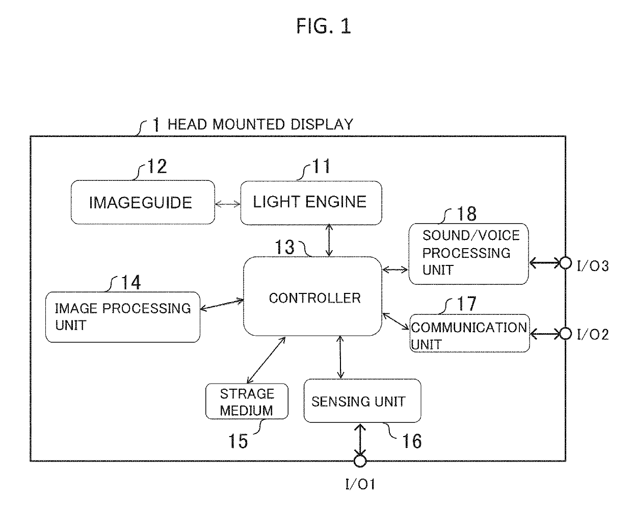
[0019]FIG. 1 is a schematic view showing a block diagram of first embodiment of a head mounted display with an imageguide in the present invention.

[0020]A head mounted display 1 is a see-through type head mounted display and is mounted with a light engine 11, an imageguide 12, a controller 13, an image processing unit 14, a storage medium 15, a sensing unit 16, communication unit 17, a sound / voice processing unit 18, and input / output section I / O1, I / O2, I / O3.

[0021]The light engine 11 is an apparatus such as small size projector which has light sources, illumination optical system, micro-display and projection optical system, and projects magnif...

second embodiment

[0048]A second embodiment will be modified example of a diffraction efficiency chirping imageguide 120 mentioned in first embodiment. Present embodiment has almost same functions as the first embodiment but parts of function are different. In the drawings, components with the same functions are denoted by the same reference characters.

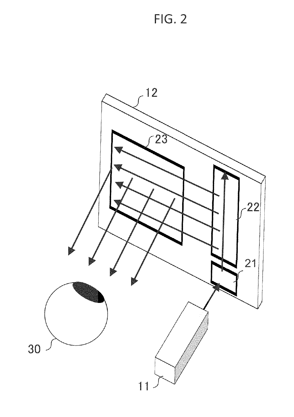
[0049]Multi layered imageguide where propagating layer is separated by color signal light is effective to propagate full-color signal light in the imageguide since large wavelength dependence of surface relief grating. FIG. 6 is schematic view showing double layered imageguide. That is, the imageguide has multi layered structure that multiple imageguide substrates formed the first, second and third hologram areas are stacked. In the examination by the author, considering diffraction characteristics of surface relief grating, a first imageguide (first light propagating layer) 121 which propagate blue to green signal light is placed near side of eye and ...


PUM


Abstract

An imageguide comprising glass or plastic planer substrate, a first hologram area, a second hologram area, and a third hologram area which are formed on the substrate as surface relief grating, period and direction of diffraction structure of the first, second, and third hologram areas have a relationship which is a sum of grating vectors of the first, second, and third hologram areas becomes zero, depth of diffraction structure on the first hologram area is a uniform in the own hologram area, and depth of diffraction structure on the second or third hologram area is chirped in the own hologram area increases luminance and uniformity of virtual image.

Description

BACKGROUND OF THE INVENTION(1) Field of the Invention[0001]The present invention relates to an Imageguide for head mounted display which displays a virtual image in user's field of view.(2) Description of Related Art[0002]For example, U.S. Pat. No. 9,791,696-B2 discloses “An apparatus for use in replicating an image associated with an input-pupil to an output-pupil includes a planar optical waveguide including a bulk-substrate, and also including an input-coupler, an intermediate-component and an output-coupler. The input-coupler couples light corresponding to the image into the bulk-substrate and towards the intermediate-component.”[0003]An Imageguide which has transparent planer form displays a virtual image in user's field of view by propagating signal light. The signal light propagating in the substrate of imageguide encounter a hologram area several times. Signal light loss by unexpected diffraction at the hologram area decreases luminance of the image and luminance uniformity ...

Claims


Application Information

Patent Timeline
IPC IPC(8): G02B27/01G03H1/04G02B27/09
CPCG02B27/0172G03H1/04G02B27/0944G02B6/34G02B2027/0105G02B2027/0123G03H1/0244G03H2001/2226G03H2001/261G03H2223/16
Inventor NAKAMURA, TOSHITERUTAKASHIMA, YUZURU
Owner THE ARIZONA BOARD OF REGENTS ON BEHALF OF THE UNIV OF ARIZONA
Why Eureka
Try Eureka