System and method for operating a system

a technology of system and method, applied in the direction of dynamo-electric converter control, dynamo-electric gear control, instruments, etc., can solve the problems of uncomplicated production of drive system, uncomplicated production of converter, and thus uncomplicated production of power supply lines and discharge lines

Active Publication Date: 2019-08-15
SEW-EURODRIVE GMBH & CO KG
View PDF0 Cites 2 Cited by
  • Summary
  • Abstract
  • Description
  • Claims
  • Application Information

AI Technical Summary

Benefits of technology

[0007]Example embodiments of the present invention provide a drive system that is able to be produced in a cost-effective manner.

Problems solved by technology

As a result, the drive system is uncomplicated in its production.
In addition, the converter is uncomplicated to produce in that, for example, recesses may be produced in the housing wall in which plug-connector parts will then be able to be accommodated.
The power-supply lines and the discharge lines are thus uncomplicated to produce with the aid of plug connections.
In addition, the converter is uncomplicated in its production in that, for example, recesses are able to be produced in the housing wall in which plug-connector parts may then be accommodated.

Method used


Image

  • System and method for operating a system
  • System and method for operating a system
  • System and method for operating a system

Examples


Embodiment Construction

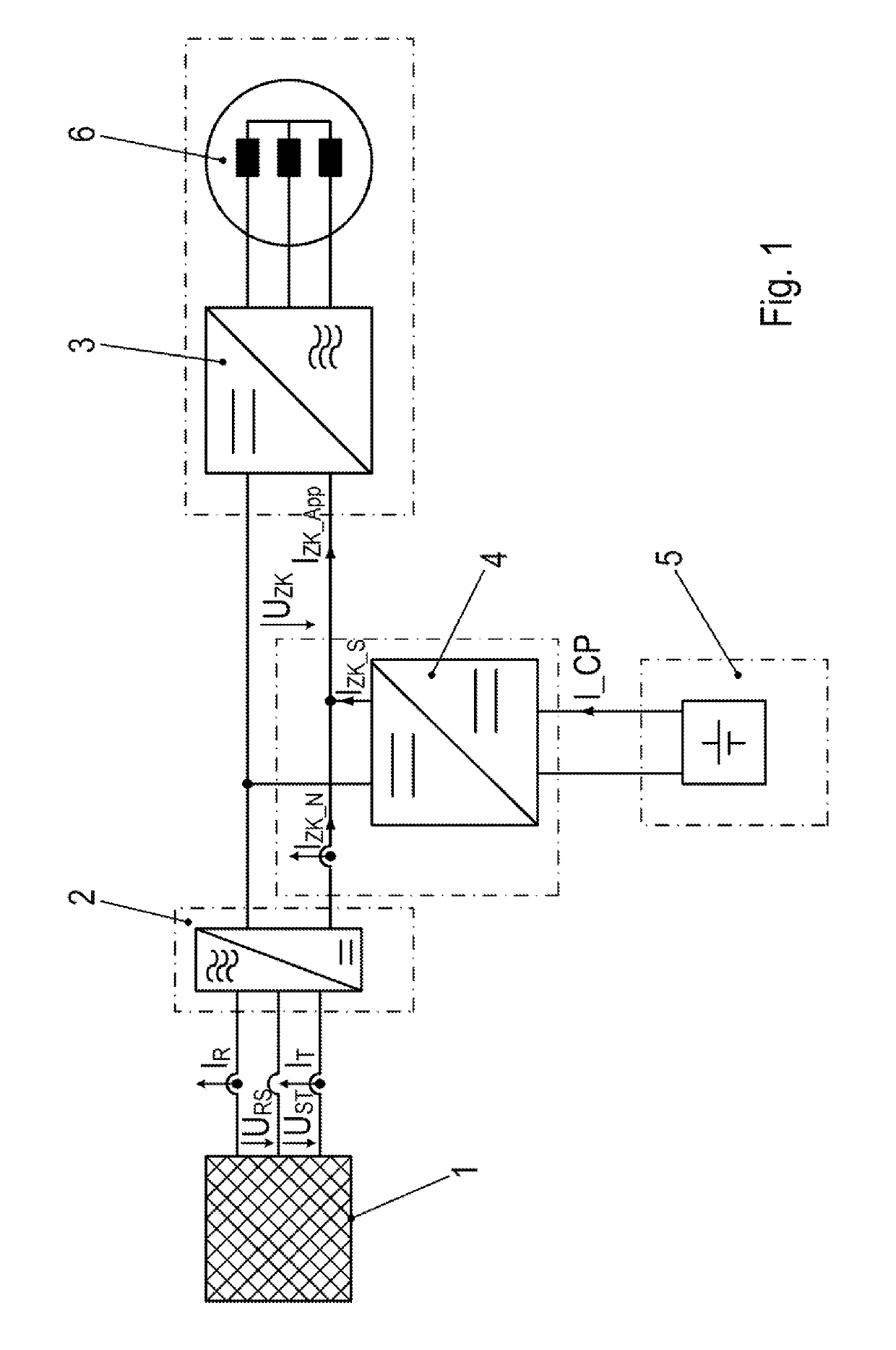
[0028]As illustrated in FIG. 1, a rectifier 2 is supplied at its AC-voltage side connection from a three-phase AC-voltage supply network 1. Toward this end, three network phase lines are provided, and current acquisitions (I_R, I_T) are provided in at least two of the three phase lines.

[0029]The respective voltages existing between the phase lines are denoted by U_RS, U_ST and U_TR, respectively.

[0030]The voltage U_ZK, i.e. the intermediate-circuit voltage, is applied at the DC side connection of rectifier 2. Current I_ZK_N emerges from the DC side connection of rectifier 2.

[0031]Instead of the current acquisitions on the network side, it is also possible to use an acquisition of current I_ZK_N.

[0032]The DC side connection of a DC / DC converter 4 and the DC side connection of an inverter 3 supplying an electric motor 6 are switched in parallel and are able to be supplied from the DC side connection of rectifier 2, the DC side connection of rectifier 2 particularly also being switched...


PUM


Abstract

In a system and method for operating a system having a rectifier which is supplyable from an electric AC-voltage supply network, an inverter which feeds an electric motor, and a DC/DC converter which is connected to an energy accumulator, the DC-voltage side connection of the inverter is connected to the DC-voltage side connection of the rectifier, in particular, the electric motor is supplied from the AC-voltage side connection of the inverter, a first DC-voltage side connection of the DC/DC converter is connected to the DC-voltage side connection of the rectifier, in particular, the DC-voltage side connection of the inverter and the first DC-voltage side connection of the DC/DC converter are connected in parallel, the DC/DC converter has a housing in which a device for current acquisition is situated, which acquires either the current, in particular network phase currents, flowing into the rectifier at the AC-voltage side connection of the rectifier, or the current emerging from the rectifier at the DC-voltage side connection of the rectifier, and the acquired value is forwarded to a signal electronics situated in the housing of the DC/DC converter, which generates control signals for semiconductor switches of the DC/DC converter.

Description

FIELD OF THE INVENTION[0001]The present invention relates to a system and a method for operating a system.BACKGROUND INFORMATION[0002]The rotational speed of a three-phase motor can be varied with the aid of an inverter by which it is supplied.[0003]U.S. Patent Application Publication No. 2007 / 0137945 describes a lift control.[0004]Japanese Patent Document No. H06-225458 describes a power control method.[0005]PCT Patent Document No. WO 01 / 74699 describes a method for reducing the power of the network connection of lift systems.[0006]German Patent Document No. 10 2013 006 964 describes a device for operating a system.SUMMARY[0007]Example embodiments of the present invention provide a drive system that is able to be produced in a cost-effective manner.[0008]According to an example embodiment of the present invention, a system has a rectifier which is able to be supplied from an electric AC-voltage supply network, an inverter which feeds an electric motor, and a DC / DC converter which i...

Claims


Application Information

Patent Timeline
Patent Type & Authority Applications(United States)
IPC IPC(8): H02M5/42H02M3/335H02M7/00H02P27/08H02P21/22H02J7/00
CPCH02P21/22H02J7/0072H02M5/42H02M3/33576H02M7/003H02P27/08H02M3/158H02M3/1582H02M5/458H02M1/0019H02M1/0009H02M3/1586H02J7/0071
Inventor SCHMIDT, JOSEFHAUCK, MATTHIASWEBER, JOCHEN
Owner SEW-EURODRIVE GMBH & CO KG
Why Eureka
Try Eureka