
Optical communication device

a communication device and optical technology, applied in the field of optical communication devices, can solve the problems of reducing the communication link margin, unable to accurately capture the location, and unable to achieve the effect of reducing the margin of communication, so as to achieve the effect of reliable and accurate location acquisition

Active Publication Date: 2019-08-15
BAE SYSTEMS PLC
View PDF5 Cites 12 Cited by
  • Summary
  • Abstract
  • Description
  • Claims
  • Application Information

AI Technical Summary

Benefits of technology

The patent aims to solve the problem of a lens used to focus light being dependent on the angle at which it enters the system, which can cause the focused spot on the detector to become displaced. Additionally, the patent seeks to improve the location tracking of the detector by using a beacon signal that can identify friendly or foe signals, ensuring that the system can avoid unnecessary or potentially damaging acquisitions.

Problems solved by technology

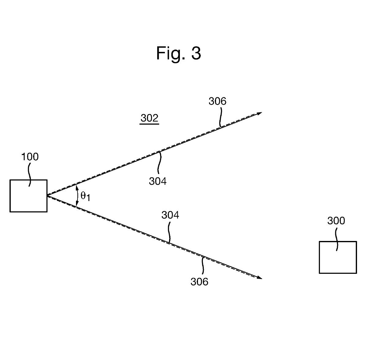
The present inventors have further realised that using an optical beam with large divergence, for example to illuminate the area surrounding the transmitting node to ensure that the other each node receives some optical power, tends to be very power inefficient since most of the transmitted optical power does not reach the detector of the opposing node.
Thus, large incidence angles may result in all or part of the spot being displaced from the centre of the communications detector, thereby reducing the communication link margin.
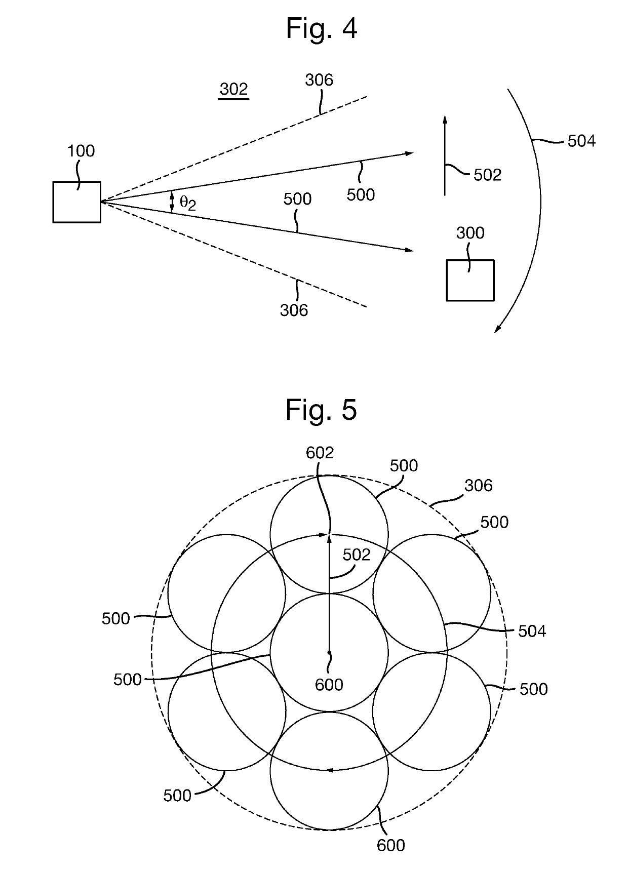
The present inventors have further realised that scanning a narrow / collimated light beam across an angular region of uncertainty may be inefficient.
However, the present inventors have realised that, for such a system and method, scanning a large angular search area with a narrow beam may take significant amount of time.
Thus, acquiring the communication link tends to use increased time and / or power.
Hence, if conditions happen to be favourable (for example, the distance between nodes is relatively short range, and / or the water through which communications are to occur is relatively clear), time may be wasted scanning the search area with a collimated beam of very high irradiance, when a scan with a larger beam (with lower irradiance) may provide the AoA sensors of the nodes with sufficient power to enable location of the other node.

Method used


Image

  • Optical communication device
  • Optical communication device
  • Optical communication device

Examples


Embodiment Construction

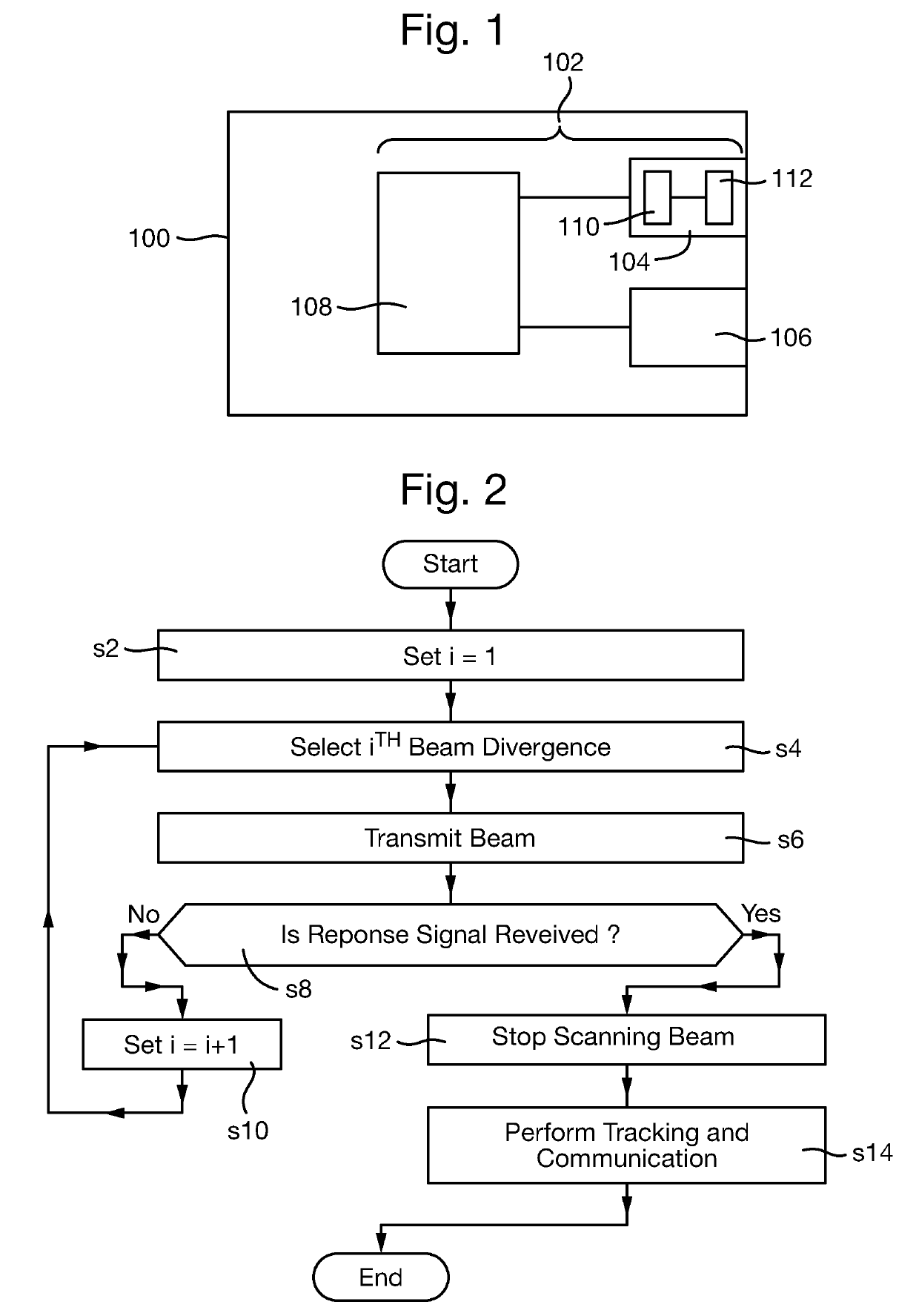
[0041]FIG. 1 is a schematic illustration (not to scale) showing an example vehicle 100 in which an embodiment of an optical communications system 102 is implemented.

[0042]The vehicle 100 is an unmanned, submersible (or underwater) vehicle, i.e. a vehicle that is configured to operate while submerged, for example, in water.

[0043]In this embodiment, the optical communications system 102 comprises an optical signal transmitter 104, an optical signal detector 106, and a processor 108.

[0044]The optical signal transmitter 104 is configured to transmit an optical signal (such as a laser beam) from the vehicle 100, as described in more detail later below with reference to FIGS. 2 to 9. In this embodiment, the optical signal transmitter 104 comprises an optical signal generator 110 and lens 112.

[0045]The optical signal generator 110 is configured to generate an optical signal, and send the generated optical signal to the lens 112 for transmission from the vehicle 110. The optical signal gene...


PUM


Abstract

Apparatus for and method of transmitting an optical signal by a Free Space Optical, FSO, communication system, the method comprising: transmitting, by an optical signal transmitter (104), an optical signal (700) into at least part of a volume of an optical medium (302); and controlling, by a controller, the optical signal transmitter (104), to scan the at least part of the volume (302) using the optical signal (700) in a sequence of non-overlapping loops (704, 708). The sequence of non-overlapping loops (704, 708) may be a sequence of non-overlapping, concentric circular loops.

Description

FIELD OF THE INVENTION[0001]The present invention relates to optical communication devices.BACKGROUND[0002]Free Space Optical (FSO) communications systems are well known for their ability to provide high data rate communications links. A FSO communication system typically consists of a pair of nodes or communication devices. Each node typically comprises an optical source, for example a laser or light emitting diode (LED), and an optical receiver. In use, the optical source of each node is aligned with the optical receiver of the other node. Modulation of optical signals emitted by the optical sources allows for the bidirectional transfer of data between the two nodes. Thus, there is a datalink between the nodes.[0003]Most current FSO systems are mounted in fixed positions on the Earth and are manually aligned with each other. Commercial systems are available which can offer data rates of several Giga-bits per second (Gbps) over a range of several kilometres.[0004]It is desirable to...

Claims


Application Information

Patent Timeline
Patent Type & Authority Applications(United States)
IPC IPC(8): H04B10/112G02B26/12H04B10/80
CPCH04B10/1123G02B26/127H04B10/80H04B10/112H04B13/02
Inventor GRIFFITH, MICHAEL STEWARTWILLIAMS, ANDREW JAMES
Owner BAE SYSTEMS PLC
Learn More