Strip cooling apparatus

Inactive Publication Date: 2019-08-22
PRIMETALS TECH USA
View PDF4 Cites 0 Cited by
  • Summary
  • Abstract
  • Description
  • Claims
  • Application Information

AI Technical Summary

Benefits of technology

[0005]According to one aspect of the invention, there is provided a cooling system. The cooling system includes a target material and a plenum or header structure. A plurality of nozzle structures are coupled to the plenum or header structure that provides a uniform flow stream from each nozzle structure. The nozzle structures are angled away from the center of the target material as well as being angled in the direction of travel of the target material so as to improve cooling uniformity by providing independent fluid paths from each of the nozzle structures to the edge of the target material reducing the interaction of fluid streams from adjacent nozzle structures.
[0006]According to another aspect of the inventio

Problems solved by technology

These apparatuses are easy to fabricate but cannot achieve higher heat transfer coefficients without s

Method used


Image

  • Strip cooling apparatus
  • Strip cooling apparatus
  • Strip cooling apparatus

Examples


Embodiment Construction

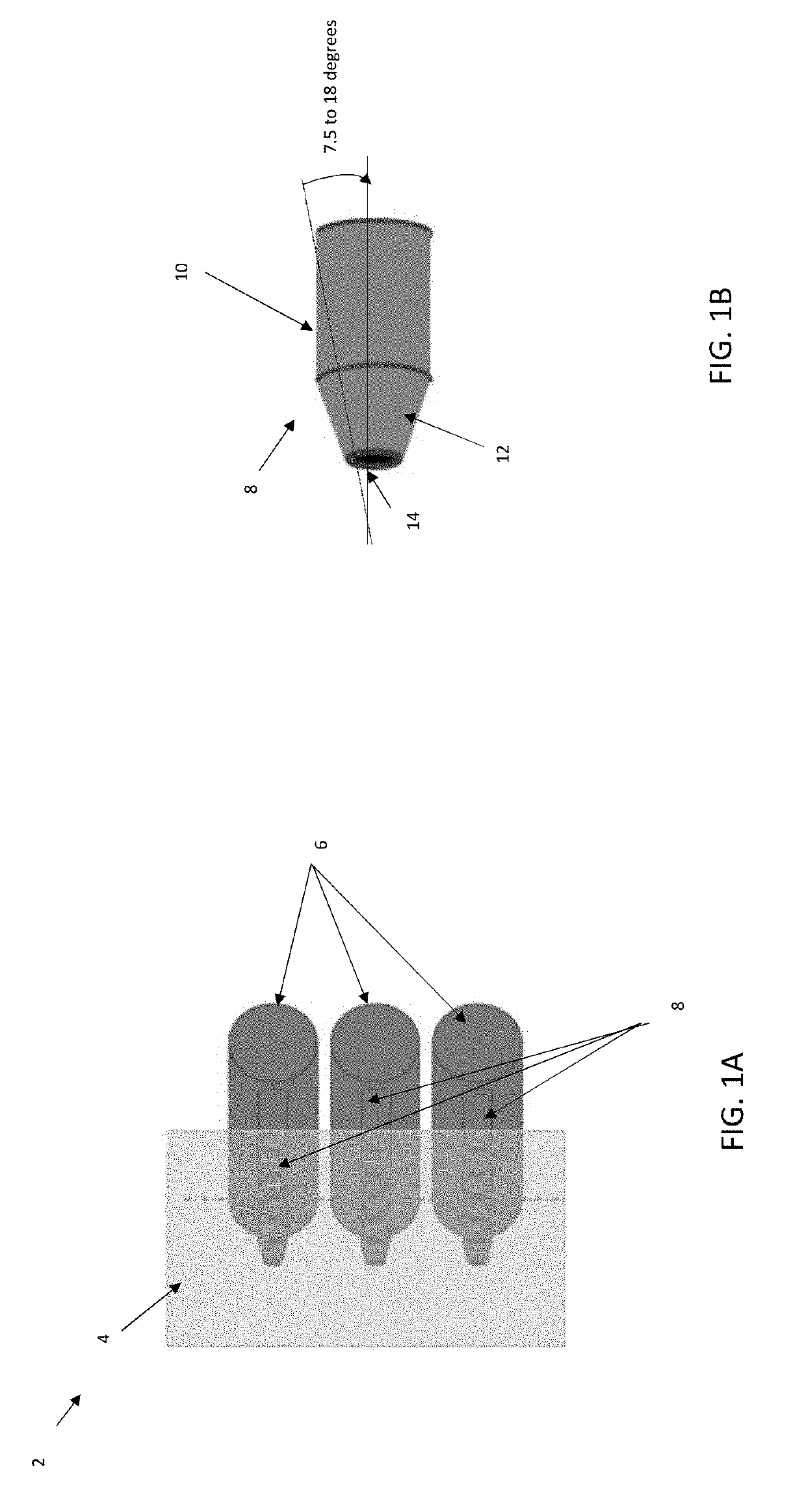
[0010]The invention describes a nozzle design for reducing cross-section at discharge and providing for a uniform flow stream from each nozzle, regardless of the dynamics of the fluid flow within the plenum or header arrangement. In addition to being angled (laterally) away from the center of the target material, the nozzles are angled (longitudinally) in the direction of travel of the target material or away from the direction of travel. This feature improves cooling uniformity by providing independent fluid paths from each nozzle to the edge of the work thereby reducing the interaction (mixing) of fluid streams from adjacent nozzles.

[0011]FIGS. 1A-1B are schematic diagrams illustrating an embodiment of the invention that utilizes a nozzle with a reduced cross-section. The arrangement 2 includes a number of tapered nozzle structures 8 formed from a plenum or header 6, as shown in FIG. 1A. The tapered nozzle structures 8 have a reduced cross section at discharge. This allows for a u...


PUM


Abstract

A cooling system is provided includes a target material and a plenum or header structure. A plurality of nozzle structures is coupled to the plenum or header structure that provides a uniform flow stream from each nozzle structure. The nozzle structure are angled away from the center of the target material as well as being angled in the direction of travel of the target material so as to improve cooling uniformity by providing independent fluid paths from each of the nozzle structures to the edge of the target material reducing the interaction of fluid streams from adjacent nozzle structures.

Description

PRIORITY INFORMATION[0001]This application claims priority from provisional application Ser. No. 62 / 631,667 filed Feb. 17, 2018, which is incorporated herein by reference in its entirety.BACKGROUND OF THE INVENTION[0002]The invention is related to the field of cooling systems, and in particular to strip cooling apparatus.[0003]Most conventional cooling systems use convection, so the cooling fluid must be directed to impinge on the work. The cooling rate per unit of surface area is a function of the temperature of the target material, the temperature of the cooling fluid and the heat transfer coefficient at their common boundary. Common methods for directing the cooling fluid include holes or slots cut in plenums which face the work. Pipe or box headers may also be used in place of the plenums. These apparatuses are easy to fabricate but cannot achieve higher heat transfer coefficients without significant increases in supplied fluid energy as well as a resulting instability (flutter)...

Claims


Application Information

Patent Timeline
IPC IPC(8): B05B1/06B05B12/08
CPCB05B1/06B05B12/087B05B11/0002B21B45/0218B21B45/0233
Inventor STEDGE, JOHN G.LARSEN, WILLIAM T.
Owner PRIMETALS TECH USA
Why Eureka
Try Eureka