Signal separator for a multi-beam charged particle inspection apparatus

a technology of signal separator and inspection apparatus, which is applied in the direction of electrical apparatus, electric discharge tubes, basic electric elements, etc., can solve the problems of heavy system and bulky system, and achieve the effect of at least reducing the effect of magnetic stray fields

Active Publication Date: 2019-08-22
TECH UNIV DELFT +1
View PDF0 Cites 39 Cited by
  • Summary
  • Abstract
  • Description
  • Claims
  • Application Information

AI Technical Summary

Benefits of technology

[0024]In an embodiment, the magnetic deflection unit is at least substantially surrounded by a frame of ferromagnetic material, which is configured to close the magnetic flux lines outside a volume occupied by the trajectories of the charged particle beams. The returning magnetic fields are effectively confined within said frame of ferromagnetic material and the effect of magnetic stray fields is at least reduced, and preferably substantially nullified.

Problems solved by technology

A disadvantage of the system as disclosed in U.S. Pat. No. 6,774,646 is, that it requires large pole pieces which are arranged above and below the electron beam inspections assembly, to provide a uniform magnetic field, which large pole pieces result is a bulky and extremely heavy system.

Method used


Image

  • Signal separator for a multi-beam charged particle inspection apparatus
  • Signal separator for a multi-beam charged particle inspection apparatus
  • Signal separator for a multi-beam charged particle inspection apparatus

Examples


Embodiment Construction

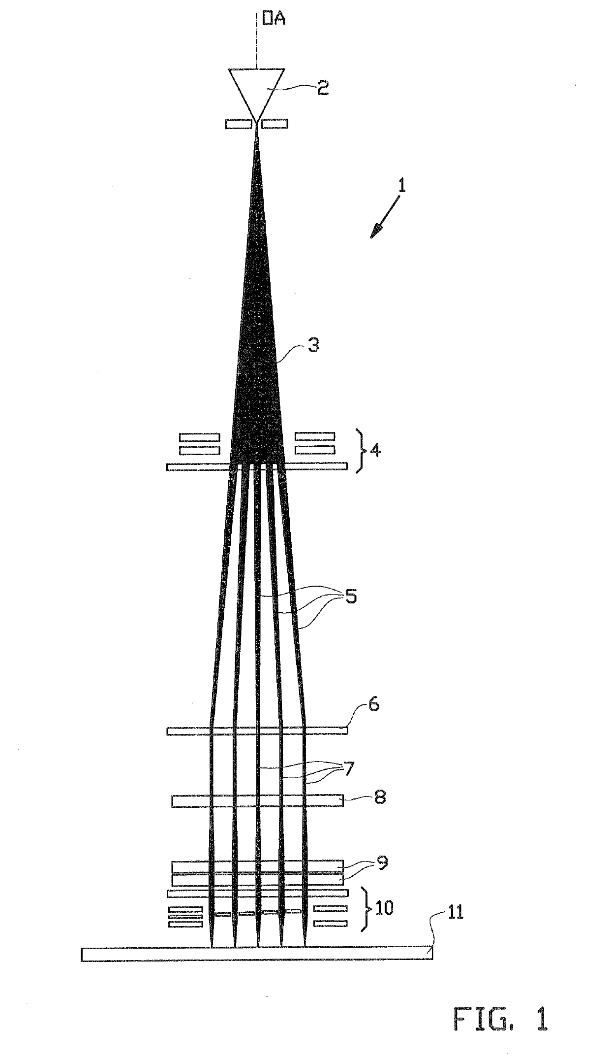
[0056]FIG. 1 shows a schematic representation of a multi-beam charged particle column 1 comprising an emitter 2, which is arranged substantially on an optical axis OA, for generating a diverging charged particle beam 3 which extends along said optical axis OA. Preferably, said emitter 2 comprises a Schottky source.

[0057]Downstream from said emitter 2, a lens array 4 is provided, which lens array 4 is provided with an aperture array for splitting the diverging charged particle beam 3 in multiple primary charged particle beams 5; each aperture of said aperture array provides one primary charged particle beam 5. In addition the lenses of the lens array 4 focuses each individual primary charged particle beam 5 at or near a collimator lens 6, which is arranged at a side of the lens array 4 facing away from the emitter 2.

[0058]Accordingly, the emitter 2 and the lens array 4 constitutes an arrangement for creating multiple primary charged particle beams 5, which multiple primary charged pa...


PUM


Abstract

A multi-beam charged particle column for inspecting a surface of a sample includes a source for creating multiple primary charged particle beams which are directed towards the sample, an objective lens unit for focusing the primary charged particle beams on the sample, a detector for detecting signal charged particles from the sample, and a magnetic deflection unit arranged between the detector and the sample. The magnetic deflection unit includes a plurality of strips of a magnetic or ferromagnetic material. At least two strips of the plurality of strips are located at opposite sides of a trajectory of a primary charged particle beam and within a distance equal to a pitch of the trajectories of the primary charged particle beams at the magnetic deflection unit. The strips are configured to establish a magnetic field having field lines substantially perpendicular to the trajectories of the primary charged particle beams.

Description

[0001]Embodiments of the invention relate to a signal separator for use in a multi-beam charged particle inspection apparatus. Embodiments of the invention further relate to a multi-beam charged particle inspection apparatus comprising such a signal separator and a method for inspecting a surface of a sample, using such a multi-beam charged particle inspection apparatus.BACKGROUND[0002]One of the routine steps in the production process of integrated circuits is the inspection of patterned surfaces, especially when starting up a new design. A substantial part of the whole 300 mm wafer is imaged to check for defects in the pattern and for particles imbedded in the pattern or on top of the wafer. This kind of inspection is presently performed by high-throughput optical microscopy in dedicated instruments.[0003]With the progress in lithography, the instruments must detect smaller and smaller defects and particles. A problem is that the light scattering from particles rapidly decreases w...

Claims


Application Information

Patent Timeline
Patent Type & Authority Applications(United States)
IPC IPC(8): H01J37/147H01J37/244H01J37/22
CPCH01J37/147H01J37/244H01J37/224H01J37/226H01J2237/152H01J2237/151H01J37/1475H01J37/28H01J2237/1508H01J2237/2445H01J2237/2448H01J2237/24592
Inventor KRUIT, PIETERNAFTALI, RON
Owner TECH UNIV DELFT
Why Eureka
Try Eureka