Flow battery regulation and control method, regulation and control system thereof, and flow battery

Active Publication Date: 2019-08-22
DALIAN RONGKE POWER
View PDF0 Cites 4 Cited by
  • Summary
  • Abstract
  • Description
  • Claims
  • Application Information

AI Technical Summary

Benefits of technology

The present invention provides a flow battery control method, system, and flow battery that have the advantage of accurately detecting the state of charge (SOC) of the electrolyte in both positive and negative electrolyte storage tanks, by averaging the detection results over a certain period of time. This ensures continuous operation of the flow battery under an optimal condition and reduces the power consumption of a circulation pump. Additionally, the flow battery can be charged or discharged while maintaining an optimal SOC, which avoids side reactions and capacity decay. This results in improved charging and discharging efficiency.

Problems solved by technology

1. during the operation of the flow battery, the electrolyte in the positive and negative electrolyte storage tanks flows through liquid delivery pipelines and cell stacks under the impetus of a circulation pump, and undergoes an electrochemical reaction in the cell stacks, such that the concentration of active materials of electrolyte entering the cell stacks changes, and then the electrolyte returns to the positive and negative electrolyte storage tanks and is mixed with the electrolyte in the storage tanks. Since there is a certain distance between an electrolyte outlet and an electrolyte inlet of the positive and negative electrode electrolyte storage tanks, the SOCs of the electrolyte in the positive and negative electrolyte storage tanks are distributed in a gradient when the flow battery is charged and discharged. Since SOC of the electrolyte at the inlet or outlet of the cell stack is only considered in an SOC detection method of the flow battery in the prior art, rather than a comprehensive consideration of SOC conditions of all the electrolyte in the electrolyte storage tanks, the detection results are not accurate and cannot reflect the actual SOC of the flow battery.
2. There are many operating state parameters of the flow battery. At present, the electrolyte flow control of the flow battery is relatively simple. The circulation pump is controlled only according to the output power requirements, and different demands of different electrolyte temperatures, SOCs, capacity decay rates and charge and discharge powers on reactants of the electrolyte are not considered. Therefore, the flow battery cannot intelligently control the electrolyte flow rate with reference to various operating state parameters, resulting in increased power consumption of the circulation pump and reducing the efficiency of the flow battery.
3. When the flow battery is being charged, the charge cutoff condition is usually achieved by setting the upper limit of a charge voltage. The upper limit of the charge voltage in the prior art is set to a fixed value. Since the flow battery is prone to side reactions under a high SOC condition, long-term high SOC charging can cause the capacity decay of the flow battery. In addition, under a low SOC condition, the flow battery cannot achieve more power input due to the limited cutoff voltage, which causes the chargeable capacity and energy efficiency of the flow battery to be affected.
4. The flow battery generates a certain amount of heat during the charging and discharging operations, and the prior art does not fully consider the heat dissipation problem of the flow battery. If the heat accumulated in the cell stacks and electrolyte cannot be dissipated as soon as possible, the long-term thermal shock will harm the performances of key materials (electrodes, bipolar plates, electrolytes, etc.) and electrolyte circulation system components (pipe fittings, valves, etc.), thereby reducing the long-term operation reliability of the flow battery.

Method used


Image

  • Flow battery regulation and control method, regulation and control system thereof, and flow battery
  • Flow battery regulation and control method, regulation and control system thereof, and flow battery
  • Flow battery regulation and control method, regulation and control system thereof, and flow battery

Examples


Embodiment Construction

[0108]In order to illustrate the objectives, technical solutions and advantages of the embodiments of the present invention more clearly, the technical solutions in the embodiments of the present invention are clearly and completely described below with reference to the accompanying drawings in the embodiments of the present invention. It is apparent that the described embodiments are a part of the embodiments of the present invention, rather than all of the embodiments. All other embodiments obtained by those of ordinary skill in the art based on the embodiments of the present invention without paying creative work fall within the protection scope of the present invention.

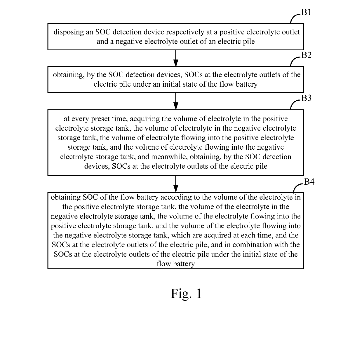
[0109]As shown in FIG. 1, a flow battery control method comprises the following steps: step B1: disposing an SOC detection device respectively at a positive electrolyte outlet and a negative electrolyte outlet of an cell stack;

[0110]step B2: obtaining, by the SOC detection devices, SOCs at the electrolyte outlets ...


PUM


Abstract

A flow battery has a control system and a control method to control the operation of the flow battery. The control method includes disposing an SOC detection device respectively at a positive electrolyte outlet and a negative electrolyte outlet of a cell stack; obtaining, by the SOC detection devices, SOCs at the electrolyte outlets of the cell stack under an initial state of the flow battery; at every preset time, acquiring the volume of electrolyte in the positive electrolyte storage tank, the volume of electrolyte in the negative electrolyte storage tank, the volume of the electrolyte flowing into the positive electrolyte storage tank, and the volume of the electrolyte flowing into the negative electrolyte storage tank, and meanwhile, obtaining, by the SOC detection devices, SOCs at the electrolyte outlets of the cell stack; and obtaining SOC of the flow battery.

Description

TECHNICAL FIELD[0001]The present invention belongs to the field of flow batteries, in particular to a flow battery control method, a flow battery control system and a flow battery.BACKGROUND ART[0002]A flow battery has numerous advantages, such as flexible design (power and capacity can be designed independently), long service life, good charge and discharge performances, free site selection, high energy efficiency, safety and environmental protection, low maintenance cost and easy realization of large-scale storage than other conventional batteries possess. In practical applications, the flow battery can be widely used as an energy storage system for renewable energy power generation systems such as wind energy and solar energy, so that the generated electric power can be continuously and stably outputted; the flow battery can also be used to cut peaks and fill valleys for an electric grid, store the electric power at the valley of electricity consumption, and output it at the peak...

Claims


Application Information

Patent Timeline
IPC IPC(8): H01M8/04992H01M8/18H01M8/04537H01M8/0432H01M8/04858H01M8/04701
CPCH01M8/04992H01M8/188H01M8/04619H01M8/04328H01M8/04335H01M8/0488H01M8/04559H01M8/04701H01M8/04313H01M8/04402H01M8/0441H01M8/0432H01M8/04753H01M8/04552H01M8/04955H01M8/04007H01M8/04768Y02E60/50H01M8/04
Inventor CHIGAN, TINGZHANG, HUAMINMA, XIANGKUNWU, JINGBOLV, SHANQIANGCHEN, NING
Owner DALIAN RONGKE POWER
Why Eureka
Try Eureka